Controller installation pays off for North Sea oil terminal

Installation of a multivariable controller at a crude oil stabilization plant at BP Amoco's Grangemouth, Scotland, oil terminal has helped reduce fuel consumption, loss to flare, and the probability of cut backs in North Sea crude oil production.
An audit pegged simple payback time at 3 months.
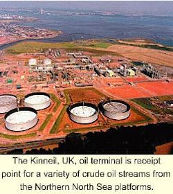
Numerous projects are under way to prepare the oil terminal at Kinneil, Grangemouth (Fig. 1), for future changes in feed flow and composition.
As part of this effort, the Honeywell RMPCT multivariable controller was installed on the front end of the plant where dissolved gas is separated from crude oil.
Some aspects of this application differ from what is normally encountered in refinery advanced control applications. The controller actively avoids capacity limits, whereas most applications seek to push units to their limits.
Moreover, this application is the first completed from a larger overall optimization effort that will cover the downstream distillation section as a next step.
Kinneil terminal
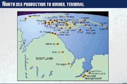
The oil-separation terminal at Kinneil receives crude oil from various platforms in the North Sea (Fig. 2) through the Forties Pipeline System. It separates the oil into stabilized crude, ready for shipping and further processing at the neighboring refinery; liquid gas products; and uncondensable gas which is locally processed as chemicals feedstock.
Various developments in the North Sea will result in changes in the next few years to the composition and flow rate of the feed to Kinneil towards a feed more rich in gas. A number of studies and projects have been under way to prepare for these changes.
Processing at Kinneil is currently already constrained for gas processing. Gas slugs occurring regularly in the crude oil feed may upset the plant and bring it close to trips. The studies identified a need for control applications that distribute the load equally over the available process capacity at Kinneil to keep individual equipment away from their limits and hence better utilize the existing capacity.
In August 1996, BP Oil Ltd. engaged Honeywell Hi-Spec Solutions, Amsterdam, to perform a control-application engineering study at Kinneil. This was granted as the first step of an advanced control project to design, implement, and commission advanced control and on-line optimization functions on that unit.
Based on the study results, the company decided to modify the basic instrumentation to provide a more stable operation and to facilitate subsequent implementation of advanced control and on-line optimization.
Three-train process
The Kinneil oil terminal receives crude oil from more than 30 North Sea platforms through a high-pressure pipeline. The process consists of three separation trains that separate gas from the crude oil to meet stabilized crude oil Reid-vapor-pressure specification for shipping and further processing.
The gas is split into dry gas containing C2 and lighter, propane (C3s), butane (C4s), and C5+. All product streams from the three trains are combined.
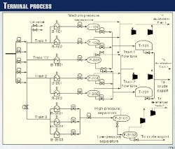
A simplified process overview is provided in Fig. 3.
The pipeline enters the Kinneil terminal at a manifold that splits the flow into streams going to the three trains. The pipeline pressure has a nominal value of 19 bar (276 psi) but may vary 17-30 bar. A pressure lower than 13 bar or higher than 40 bar will cause problems in the pipeline system.
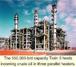
Trains 1 and 2 are identical; Train 3 has a different layout (Fig. 4). Trains 1 and 2 together have a capacity of 680,000 b/d; Train 3, of 550,000 b/d. Total throughput is limited for safety reasons to the maximum crude relief capacity of 1.15 million b/d.
Each of Trains 1 and 2 has two dedicated heaters followed by medium-pressure (MP) separator drums. A fifth heater and MP separator are shared by the two trains. The gas and liquid streams from the fifth separator (F-801; Fig. 3) can be distributed at an adjustable ratio to the two trains.
The heaters dedicated to individual trains may use the exhaust gas from the compressor turbines. They also may have auxiliary firing with fuel gas, if the operator decides to light the burners. The fifth shared heater is fired on fuel gas only, so that no waste heat is recovered here. The heaters may be limited on heating duty, especially if the auxiliary firing is off.
Valves at the drum inlet control the flows to the five-train first and second MP separators. Valves at the drum outlets control the drum liquid levels.
The drum pressure floats with the corresponding compressor suction pressure. There are high and low limits on the separator drum pressure. In case the high-pressure limit is reached, an automatic control scheme relieves the gas to flare.
Liquid out of Trains 1 and 2 separators is sent to one flow tank per train. The rest of the dissolved gas is separated here.
There is one gas compressor per train for the MP separators and one for each flow tank. The compressors are two stage and driven by a gas turbine, fueled with dry-gas product.
A local control scheme protects the compressors from surge with a spill-back line and adjusts the turbine speed to control the suction pressure. An automatic control scheme will relieve gas to flare if the suction pressure reaches a high limit.
The compressors may trip on high or low suction pressure in case the disturbances are too fast for the control schemes' reaction. More often they may trip on high level in the inter-stage liquid knock-out drum. The exhaust gas is used to heat the crude in four of the five heaters.
There are two electrically driven spare compressors, one for the separators and one for the flow tanks. The spare may replace either the corresponding Train 1 or Train 2 compressor.
The flaring system is shared by Trains 1 and 2. For safety, the total amount of raw gas to Trains 1 and 2 (gas to flare + gas and liquid from compressors) must always remain less than the relief capacity limit.
Crude entering Train 3 is heated in three parallel heaters of which two are heated with compressor turbine exhaust gas and auxiliary fuel gas firing and one heater fired on fuel gas only. There may be a heating duty limit if auxiliary firing is not lit.
The heated crude flows from the three heaters into the high-pressure separator where part of the gas flashes off. The liquid then flows to the low-pressure separator where the rest of the gas flashes off. The low-pressure separator may have a liquid removal limit if all booster pumps are not in use.
The gas from the low-pressure separator is compressed by a single-stage compressor and charged on the high-pressure compressor liquid knockout drum. The high-pressure separator gas goes directly to the high-pressure compressor knockout drum.
The high-pressure compressor is two-stage with interstage liquid knockout. The knockout drums can trip on high level. Both compressors are driven by gas turbines. Both compressors have electrically driven spares.
Each train has a gas distillation section consisting of a de-ethanizer, a de-propanizer, a debutanizer distillation column, and a dry-gas sweetening column.
The gas and the liquid from the compressors feed the de-ethanizer. It splits the feed into dry gas containing C2 and lighter overhead and C3 and heavier in the bottoms. The dry gas has a dew point specification and is sweetened in an amine absorber that brings the CO2 content under a maximum limit.
The amine absorber is limited on CO2-removing capacity. The de-ethanizer bottoms has a maximum C2 limit. The de-ethanizer is limited on reboiler heat and cooling capacity.
The depropanizer splits the de-ethanizer bottoms into C3 and C4+. The debutanizer splits further into C4 and C5+. The C3 product has a C2 and C
As Trains 1 and 2 have more storage capacity in the five MP separators and the large flow tanks than has Train 3 in its high-pressure and low-pressure separator, Trains 1 and 2 can better absorb fast feed fluctuations than can Train 3.
As Train 3 has almost the same processing capacity as Trains 1 and 2 together, however, it should take up long-term variations.
Basic control schemes
The design phase identified a need to modify existing basic control schemes. This would enable a wider range of operation for the heaters with both waste-heat recovery and auxiliary firing and, by swapping the control handles, for more direct pressure control upstream and downstream of the manifold valves at the crude entry.
This helped to stabilize plant operation. Because of the potential impact of these changes on both pipeline and separation-plant behavior, an extensive simulation study before implementation assessed behavior during abnormal situations.
Based on the operating strategies and economic environment at Kinneil, the following main objectives for supervisory control and optimization have been identified:
- Create extra gas-processing capacity by improved load distribution.
- Stabilize product qualities.
- Minimize fuel consumption.
These objectives are currently met by a single Honeywell RMPCT application, distributing the load over several pieces of parallel equipment, stabilizing crude oil Reid vapor pressure, and optimizing fuel-gas consumption.
The de-ethanizer bottom flows are currently used as an inferential indication of the loading of the distillation trains.
The next step will be to implement RMPCT applications on the nine distillation columns and to extend the optimization functionality, currently implemented with the built-in optimizer in the front-end RMPCT application, over the distillation sections as well.
This will mean that the distillation column loads will be balanced by taking into account the actual column limits, rather than inferring them from de-ethanizer bottom flows.
The Honeywell Profit Optimizer will be used for this extension of the optimization functionality by coordinating the actions of the individual RMPCT controllers and hence to achieve plant-wide optimum operation.
The remainder of this article describes the RMPCT application on the Kinneil "Front End." This is the crude oil processing and gas compression part of the plant (Fig. 3).
Front-end control
The Kinneil load-distribution multivariable control is designed to meet the following objectives by optimizing a set of manipulated variables (MVs) subject to a set of constraint or control variables (CVs):
- Distribute the load over the three trains and the five separators so that all trains are kept away from limits as long as there is capacity in another part of the unit.
- Maintain stabilized crude oil Reid vapor pressure.
- Maximize use of waste heat instead of fuel gas.
The controller manipulates the following MVs (12) -
- Flow to the five separators on Trains 1 and 2 (5).
- Flow to Train 3 (1).
- Outlet temperature on each of the five heaters on Trains 1 and 2 (5).
- Train 3 heaters combined outlet temperature (1). - to control the following CVs (42):
- Pipeline pressure (1).
- Trains 1 and 2 raw-gas flare capacity limit (1).
- Trains 1 and 2 combined throughput limit (1).
- Total combined throughput limit (1).
- Trains 1 and 2 crude oil Reid vapor pressure (1).
- Train 3 crude oil Reid vapor pressure (1).
- Combined crude oil Reid vapor pressure (1).
- Separator level-control valve positions (6).
- Heater turbine-exhaust-gas heat availability (4).
- Heater fuel-gas availability (5).
- Train 3 fired-heater minimum throughput (1).
- Gas-turbine capacity limits (6).
- Compressor's interstage liquid capacity (6).
- Train 3 booster-pump current (1).
- Amine treaters CO2 removal limit (3).
- De-ethanizer capacity limits (3).
A distinct difference from most other advanced control applications is that the main objective is to maximize the distance to several limits, rather than pushing it towards these limits.
The built in optimizer provides this functionality by minimizing the weighted sum of squares of deviations from a perfectly balanced situation. As the RMPCT built in optimizer can handle both linear program and quadratic program types of objective functions, it is ideally suited for this task.
RMPCT moves the MVs to respect the CV limits and use any remaining freedom to drive the process to the optimum point calculated by the built in optimizer.
Also, one of the CVs (pipeline pressure) behaves as an integrator: Given an imbalance between production at the North Sea and throughput at Kinneil, this CV will ramp away from its target and not reach a new steady state. Normally integrating variables have the highest control priority because they are associated with equipment inventories that must remain between limits at all times.
In this application, the situation is slightly different. The Kinneil application only has control over the emptying handle; the filling handle is controlled at the North Sea platforms.
Whenever Kinneil is at maximum capacity and the front-end controller has exhausted all its freedom fully to utilize this capacity, then Kinneil cannot absorb more crude, and the front-end controller will have to let the pipeline pressure rise.
If this situation persists for a longer period, the pressure will reach a high-pressure limit at which the pipeline operation will ask the platforms to reduce production. RMPCT could easily be configured to meet this requirement of properly prioritizing the pipeline pressure CV control relative to other objectives.
Controller performance
The controller is now firmly established as an operational tool. Operator acceptance was high from the beginning of the implementation because of operator involvement in the design phase and extensive operator training.
Significant benefits are obtained and can be summarized as:
- Steadier crude oil Reid-vapor-pressure results. This CV is now used as a way to reduce flaring by temporarily absorbing more gas in the stabilized crude, up to the Reid-vapor-pressure specification limit.
- Gas distribution has been equalized and throughput reduction requests have been minimized.
- Crude oil is now directed to the heaters where heat from turbine exhaust is available. This has meant that the fuel gas used by the fired heaters has been reduced.
- Standardization of operations between shifts.

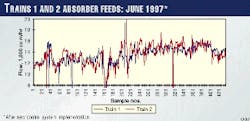
To illustrate the control system's performance, the five Trains 1 and 2 separator flows are given in Fig. 5, for Jan. 1, 1997, before implementation of the new controls, and in Fig. 6, for June 1, 1998, after implementation of RMPCT and the new basic controls. Sample period is 1 min.
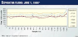
The improvement of the basic controls removes the fast cycling of the flows, while RMPCT distributes the flows optimally, as opposed to the former operator practice of using a fixed distribution. As a result, limits are better avoided and more energy is saved.
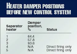
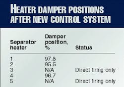
The latter is illustrated in Table 1, which lists the average damper positions of the waste-heat-recovery units during January 1997, and Table 2, which lists the positions for June 1998. A damper opening of 100% means that no exhaust gas bypasses the heater and heat recovery is at maximum.
If the raw-gas loads to each train are equalized, then the amine systems will have a greater capacity to process sour gas without reaching a limitation.
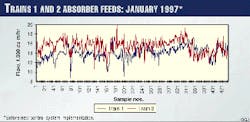
Fig. 7 shows how the amine system loads used to be unequal. The samples are hourly averages. After RMPCT was commissioned, the flows were more balanced (Fig. 8).
At the same time, product quality, measured by its Reid vapor pressure is significantly improved, as Fig. 9 shows in displaying the percentage of laboratory results within the range ±0.5 psi of the target. This has been recorded over the last few years, each sample being the percentage of results during a month that are within the range.
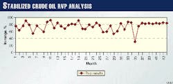
Month 37 is January 1998 when RMPCT was commissioned. Results before RMPCT was commissioned are much more erratic.
As a result of a combination of inaccuracies caused by sampling and testing techniques, the accuracy of the laboratory result is about ±0.5 psi. This means that it is not practically possible to have 100% of results within the bounds of the specification.
The Authors

Michiel van Wijck is a senior advanced control and optimization consultant with Honeywell Hi-Spec Solutions, Amsterdam. He holds an MSc (1986) in electrical engineering from Eindhoven University of Technology, The Netherlands.

Steve Bassett is a process control engineer at BP Amoco's Kinneil crude oil stabilization plant, Grangemouth, Scotland. He holds a BEng (1984) in chemical engineering from Bradford University, England, and is a member of the Institute of Chemical Engineers.