North Sea field leaps pressure, temp. hurdles to 2000 start-up
The high pressure and temperature nature of the Shearwater field, offshore U.K. North Sea, presented significant engineering challenges as well as those inherent in producing a sales-quality gas offshore.
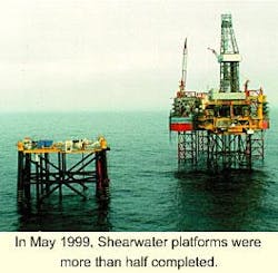
This month, the project is on track as drilling will be completed on the five Fulmar field main block wells whose production will support the platform. In May 1999, Shearwater topsides were installed on the wellhead jacket and the production jacket installed.
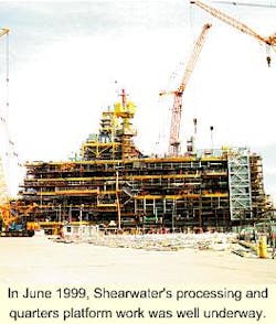
This permitted tie in and commissioning of a gas line to Bacton, England. Production facilities, being built at Wallsend, are nearing completion and will be installed in March 2000.
After 3 months' offshore connection and commissioning, first sales gas is scheduled for July 2000.
HP/HT reservoir
The Shearwater field lies 200 km east of Aberdeen in 90 m of water in the Central Graben Area of the Central North Sea, part of the P188 license. License holders are operator Shell U.K. Exploration & Production (28%), Esso Exploration & Production U.K. Ltd. (28%), ARCO British (27.5%), and Superior and Canadian Superior (Mobil) (16.5%).
At some 15,000 ft below the seabed, the reservoir is a high pressure, high temperature (HP/HT; 1,000 bar, 180° C.) gas condensate reservoir, with a ratio of 170 bbl of condensate/1 MMscf of gas with 30-ppm H2S, 3% CO2, and a high-salinity aquifer.
Initial production will be from the main block Fulmar reserves (309 million boe) with peak production rates of 425 MMscfd of sales-quality gas and 80,000 bo/d of a high vapor-pressure condensate.
The selected development concept required that a wellhead jacket be installed before start of development drilling (July 1997) and that the development wells be completed before start of production.
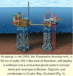
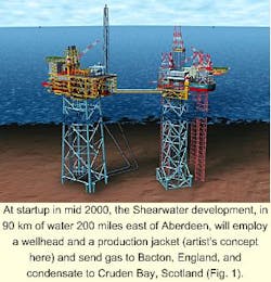
A combined processing and quarters platform will be installed in early 2000 with gas being exported via the 34 in. Shearwater Elgin Area Line (SEAL) pipeline to Bacton with the condensate being exported via the Forties Pipeline to Cruden Bay, Scotland.
Total development cost of Shearwater and associated export systems is some $1.4 billion (Fig. 1).
In 1996, the project team defined the development concept with associated cost and schedule forecasts so that they could be presented to the Shearwater coventurers for approval.
This process was completed in April 1997 with the formal sanction of the development by the U.K. Department of Trade & Industry (DTI). This permitted the detailed design work for both the process facilities and the associated gas and liquid export facilities to begin.
Drilling program - Key in HP/HT developments is the need to drill all development wells before start of production. Currently, it is technically impossible to drill into partially depleted HP/HT reservoirs. This early start to development drilling plays a large role in selection of a development concept.
The studies to define the development concept considered 10 platform configurations. To satisfy the need to drill the production wells before start of production and to reduce technical drilling risks, it was decided to install a wellhead jacket before start of drilling.
The alternative would have been to incorporate a mud-line suspension unit in the well design and install a jacket later. The significantly greater technical risks associated with making and breaking such a connection led to the choice of drilling through a preinstalled wellhead jacket.
This also had the advantage of containing all the HP/HT elements of the development on the wellhead jacket and providing a separation of some 80 m between the HP/HT drilling center and the processing facilities.
The opportunity to share the sales-quality-gas export pipeline with the nearby Elgin-Franklin development defined the process configuration. This included gas-condensate separation, gas dehydration, and a low-temperature separator process and amine plant to satisfy the sales-gas specification of both the Interconnector Pipeline and the National Transmission System.
One of the main drivers and a significant challenge to engineers was to reduce development wells. The initial development was based on the availability of existing HP/HT completions and wellheads that required up to seven production wells to be considered at the point of project sanction in April 1997.
Development work commenced with Baker and Cameron with the stated aim of producing a larger completion and a 15,000-psi wellhead that would permit the number of wells to be reduced to five, representing a significant saving on the drilling budget.
This gain, however, brought with it a high technical risk: using essentially untried equipment for Shearwater's development wells. Application of a rigorous quality management and extensive testing of the equipment onshore before its installation offshore overcame this concern.
World's first
During completion of the design, it became apparent that a reduction in the total number of wells to be drilled could be effected if the tubing size could be increased to 7 in. The use of 7-in. tubing, together with its associated completion components, required a large-bore christmas tree with a 63/8-in. valve bore rated for 15,000 psi at 350° F. and consequently API PR2 Appendix F qualification of the valves and actuators.
The valve blocks, in particular the heat treatment applied to the valve blocks, had to be reviewed after discovery through testing that the hardness values for the center of the block were below specification.
This problem was eventually resolved by enhanced heat treatment.
The completion size was increased from a 41/2-in. original design to a 7 x 51/2-in. tapered string, thus allowing the same productivity levels from fewer wells.
The large-bore nature of the completions required development and testing of a completely new suite of completion tools, including a 97/8, 15,000-psi, 375° F. packer, a 51/2 in., 13,500-psi tubing retrievable sub-surface safety valve, a 7-in., 15,000-psi wireline retrievable sub-surface safety valve and suitable landing nipples and plug systems.
All completion components were individually designed, built, and tested at the required pressure and temperature before a full system trial was conducted at the Bridge of Don facility, Aberdeen.
The Shearwater choke duty is a unique combination of high pressure, high temperature, and high gas and condensate flow rates.
Coupled with the high probability of sand production in later field life, these conditions defined an arduous service for an item of hardware that is fundamental to satisfactory operation.
Significant experimental testing has been carried out to reduce the risk of operational problems.
Testing was conducted by Elf Exploration U.K. Plc, and further developed with input from the Shell/Esso Brent field experience. This field experience was used as a starting point for the involvement of the equipment vendor.
Empirical results showed that there were marked differences in the erosion performance of the various choke designs. Analysis of the Shearwater chokes using enhanced Brent data predicted choke production life and further assisted in vendor selection.
This work also showed that it would be advantageous to install a tungsten carbide sleeve in the choke outlet. Nevertheless, the Shearwater chokes will still have a limited life at high sand-production rates.
Limited operational experience of chokes of this size led to a decision to carry out an enhanced API PR2 test to ensure that the stems' seals were satisfactory for Shearwater service.
Last in the testing programs was dynamic analysis of the flow cage. This check confirmed the choke will withstand the excitation resulting from high flow rates and high pressure differentials. This was confirmed during clean up of the third development well in November 1998.
HP/HT valves
Innovations in several areas in piping and valve engineering deviated from Shell Group and U.K. standards to design what was needed for the Shearwater project.
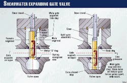
The demanding field conditions of high pressure and high temperature coupled with high CO2 and high H2S levels have necessitated exotic materials: Much of the piping is in duplex and super duplex stainless steels (Fig. 2).
The project can claim several "firsts" for Shell U.K. Exploration & Production.
For example, company standards require double-block-and-bleed isolation for maintenance on live systems. This has previously required two separate valves with a vent in between. Considerable weight, space, and cost reductions have been achieved by using in 170 locations a single expanding gate valve for double block.
High-performance butterfly valves have been tested and used for oil and gas duty for the first time on a Shell platform, and a new type of monoflange valve has been introduced to reduce risk of fatigue failure of small-bore branches. Both innovations have saved money, space, and weight.
The HP/HT end of the process required development of several prototypes because valves were simply unavailable in the sizes and pressure ratings needed.
For example, a 12-in., 15,000-psi ball and a similar slab gate valve were developed and tested, the former weighing 27 tonnes (metric tons) without its actuator.
An 8-in. expanding gate valve was also tested at full design conditions, single valves being used to provide double-block-and-bleed isolation of the 12,500-psi flowlines, and an 8-in. HPHT check valve developed to protect against flowline failure.
The prototype development programs, despite some test failures, proved that exhaustive testing under design conditions can reveal the difficulties of designing for HP/HT and can prevent failures after project start-up.
Producing sales-quality gas offshore
Sharing the gas export pipeline with the nearby Elf-operated Elgin/Franklin development represented a significant economy for both developments, permitting the sharing of infrastructure costs.
Use of a common gas export pipeline required production sales-quality gas offshore, in turn requiring both a low-temperature separator and an amine plant offshore, together with gas dehydration and compression.
The result is a complex processing plant that would compare with current onshore terminals such as the Shell/Esso St. Fergus, Scotland, facility.
The Shearwater offshore facilities produce a high-vapor-pressure condensate suitable for export via the nearby Forties Pipeline and a sales-gas product suitable for direct consumption by either the U.K. or the European gas markets.
The HP/HT nature of the Shearwater reservoir largely manifests itself in the wellhead area and front end of the process plant. The reservoir pressure is immediately reduced across the choke valves to more typical levels (90 bar) before the fluids are routed to the primary separator.
Downstream of the separator, the gas phase is cooled to assist subsequent processing, whereas the liquid fraction is maintained as hot as possible to facilitate meeting the liquid product export vapor-pressure specification.
The potential for sand production from the wells along with the probable production of highly saline formation water pose specific problems.
Sand production must be contained to avoid downstream erosion or equipment blockage. Installation of surface facilities to remove sand has been provided for should sand be produced in the early field life when it would be impossible to set sand screens downhole.
Once the reservoir pressure has declined to 10,300 psi, it will be possible to install the more conventional downhole sand screens.
The salinity of the produced water poses particular problems for material selection and demands a high separation efficiency to meet the salt-in-condensate-export-liquid specification.
The corrosivity of the reservoir fluids and the high wellhead temperatures result in the requirement for super duplex materials for much of the front-end process. Once the fluids are cooled and water removed, more conventional materials are employed.
In terms of hydrocarbon processing offshore, the gas must be conditioned to a quality suitable for direct sales to the market. This involves removal of practically all of the H2S (down to 1 ppm) while controlling the CO2 content within a specified band.
The heavy hydrocarbon and water content of the gas must be reduced to satisfy the requirements of the sales-gas specification. In addition, liquid processing requires that the light-end content of the liquid be reduced to meet liquid-export specification for pipeline entry.
Thus, the selected process configuration must ensure hydrocarbon-component separation and distribution between the two product phases so that the requirements of both gas and liquid specifications are met.
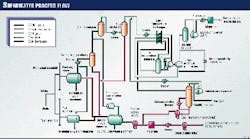
Component fractionation is therefore critical and leads to a higher degree of offshore processing than typical for U.K. offshore platforms (Fig. 3).
In general terms, liquid separation and stabilization are relatively straightforward, despite specific technical issues such as high pressure drops and the effect of shear on particle distribution.
null
The gas conditioning, however, offers more difficult challenges not only from the number and nature of the processing-unit operations required but also from their inter-relationship.
The controlling parameter for the gas-export specification is the Wobbe Index, a measure derived from both the heating value and the relative density of the gas.
In order to achieve the hydrocarbon dew point, the Shearwater process employs turboexpansion to generate the low temperature required to remove the heavy components from the gas as a separate liquid phase.
The extent of the dew point process, that is, the low temperature required, depends upon the inert content (principally CO2) of the gas phase: The lower the CO2 content of the gas, the more heavy hydrocarbons must be removed which becomes increasingly more difficult.
Thus, control of the CO2 content of the export gas ensures that product specification can be met within the limits of the installed equipment.
The cold NGLs produced by the turboexpander system move from the low-temperature gas plant to a stabilizer column where they are processed to meet the export-liquid specification. The resulting overhead gas is recycled upstream of the low-temperature gas process.
The sweetening duty of the gas is to remove the H2S from ~50 ppm vol to <1 ppm vol while simultaneously controlling the CO2 content within a limited band.The H2S level of <1 ppm vol is a very low specification, which, in the U.K., is more typically near 3 ppm vol. This, coupled with the need tightly to control the CO2 slippage to control the Wobbe index, leads to a demanding sweetening duty, which is further compounded by the fact that this equipment will be located in an offshore environment.null
In recognition of this, considerable effort was expended during the feasibility phase to assess alternative technologies to ensure that the final selection of an amine-based solvent was justified for the Shearwater sweetening duty.
The amine-based sweetening process, Exxon Flexsorb, results in the production of an acid-gas stream, consisting essentially of H2S and CO2. Environmental considerations led to the requirement to incinerate this acid gas to convert the H2S to SO2.
To avoid releasing SO2 to the atmosphere, a seawater quench system is employed to convert the SO2 to sulfate and return it to the sea where it exists naturally.
A high-fidelity training simulator has been developed during the course of the design. Not only will this be used to train operations personnel before going offshore but also to confirm commissioning and start-up strategies at the design stage.
The dynamic simulator design is of such a standard that it will be used to support design activities both in the short term and in the future.
Design flexibility
In order to capture some processing flexibility, a range of feed compositions, from rich to lean, was developed. In addition, and in recognition of the challenging nature of the process, design points were established within the limits posed by the export specifications.
Recognizing that Shearwater production facilities will be used as a future processing center for other fields in the area, key design features were included in the initial design to facilitate this.
For example, the Shearwater test separator was designed and installed as a future reception vessel, although it will be used for Shearwater well-testing purposes in the short term.
In addition, weight and space allowances and selected tie in points for future fields are included in the design in order to ease the introduction of new fields at a later date.
In addition to development of new valves for HP/HT service, as described previously, use of nonarmored cables yielded significant cost and weight savings.
Analysis of the properties of various cable types and installation conditions, particularly the effect of electrical faults, led to an understanding of the limits of the conventional wire braid armored cables normally specified for offshore duty.
This work has allowed the project to reassess a wide range of low-voltage cable characteristics necessary for North Sea installations and, in collaboration with U.K. cable and gland manufacturers, to develop one unarmored cable type and corresponding accessories that can be installed anywhere offshore.
The resulting cables are mechanically tough and resist hydrocarbon and drilling fluids, are flame retardant, and produce zero halogens when burned.
Projected cost savings and technical advantages made possible by adopting this approach, for example simplified installation and grounding methods, having only one power and instrument/control cable sheath specification, together with significant weight reduction, may become the norm for future offshore projects.
Discharge objectives
Five key environmental discharge objectives have been identified:
After it became clear that these muds were not technically feasible under Shearwater conditions, cuttings containment for onshore treatment and disposal was progressively introduced.
The Shearwater objective is to limit gas losses to 0.3% boe during normal operations. This will be achieved by use of nitrogen for flare purge and by provision of valves with enhanced sealing arrangements.
Start-up employs an innovative approach that involves import of gas from the SEAL pipeline so that the gas systems can be started up and stabilized on recycle before reservoir fluids are introduced.
This approach should reduce the total quantity of gas flared during start-up by around 60%.
It was found that incineration enhances efficiency and significantly reduces the amount of fuel gas required.
Moreover, with an incinerator, it is possible to use a seawater scrubber to convert the sulfur dioxide to sulfates, which then can be discharged to the sea with no harm to environment.
Hydrocyclones deal with the dispersed oil, and modifying the process for produced water treatment makes possible the recovery of dissolved oil so that the objective will be achieved for the total oil content.
Safety measures
During detailed design, considerable development has been apparent in understanding the explosion overpressures to which the platform would be subjected in an explosion.
Experimental work completed at the British Gas Spadeadam facility and at Shell's Thornton Research Centre have enabled calculation of the overpressures that could be encountered in the various areas of the platform.
Comprehensive analysis of the dynamic response of the structure has enabled the design of a structure able to withstand predicted overpressures.
This approach has also permitted enhancement of the design of the blast walls to ensure that the risk of temporary-refuge impairment will be reduced to as low as reasonably practicable.
A major focus for the safety of the installation has been those accidents associated with hydrocarbons, particularly in the light of emerging research information on the hazards of explosions.
Decisions on the primary structural design were necessarily taken very early in the project and the following features were included to improve the resilience to fires and explosions:
- The number of transverse trusses was increased.
- The deck beams span onto trusses, thus reducing the loads on the longitudinal trusses, which are essential for the support of the temporary refuge.
- The integrated deck retains structural integrity on loss of a jacket leg.
- Blast walls have no penetrations.
- Considerable effort has been applied to maximizing redistribution of loads and to ensuring that any weak links have been identified in, for example, the support details for the blast walls.
The structural design work has been underpinned by extensive sophisticated analysis of accidental loadings and structural response.
Close integration of the main steelwork design with that of the key vendors, the blast wall suppliers, for example, has been key.
In addition to structural engineering, the project introduced measures in many other areas that will have benefit in preventing or controlling major accidents. These include:
- Printed circuit heat exchangers.
- Nonintrusive instruments.
- Subsea pipeline isolation valves.
- New gas detector technology.
- Single gas detector process trips.
- Water deluge to reduce explosion overpressures.
- Removal of potential ignition sources.
- Optimizing equipment layout to minimize intensity of explosions.
- Installation of three transverse blast walls.
- Blast-rated dampers on quarters air inlets.
- Extensive use of passive fire protection.
- Water-filled jacket legs.
The Author
John Stubbs, Shearwater project director, graduated from Leeds University with a BS (1973) in chemical engineering and joined what was then Constructors John Brown in September 1973 as a process engineer. After 3 years, he joined Shell Exploration & Production, London, in September 1976. He has since worked in London, The Hague, Stavanger, Bangkok, and Cairo before returning to Shell Expro in 1996 to take his current post.
