Timer-controlled beam pumps reduce operating expense
A timer or pump-off controller (POC) can improve overall beam-pump efficiency for a well with a pump capacity greater than its production capacity. More than 400,000 wells in the U.S. operate with beam-pump artificial lift. Most of these wells pump 24 hr/day and have a pump capacity that exceeds the well's production capacity.
Fluid flows into the well when well bore pressure is less than reservoir pressure. In beam-pumped wells, a reciprocating pump removes that fluid. When pump capacity exceeds liquid-producing capacity, a pump could be operated periodically and still remove practically all of the fluid.
While the well is shut-in, however, the bottomhole pressure should be maintained at a low value compared to the reservoir pressure so that the maximum inflow into the well is maintained.1
An electrical, manually set, on-off timer can be used to control operating time of a pumping unit's motor. Or, an automatic pump-off-control (POC) device can monitor a parameter that relates to pump fill and shut down the pumping unit motor when partial fill or liquid no-flow is detected.
A properly operating timer or POC can reduce both electrical and maintenance costs.
An example for a well operated by Cobra Oil & Gas Corp. Wichita Falls, Tex., shows how an installation was analyzed to increase its pumping efficiency.
Pump pounding
Wells will "pound" liquid during the pump downstroke if the pump capacity exceeds a well's producing capacity. This "pounding" of the pump plunger against the liquid causes vibration throughout the entire system.
The shock loading can cause rod buckling, pump wear, tubing wear, severe rod-loading changes, and pumping-unit vibration even to the extent that the vibration can be seen and oftentimes even heard. These changes in loading are easily measured with a dynamometer.
Changes in rod loading on the downstroke also affect the pumping-unit balance and motor power requirements. Longer life will be experienced by the pump, rods, tubing, and pumping unit system if the plunger does not "pound" liquid near the middle of the downstroke. Operating the pumping system with a pump barrel full of liquid will lengthen equipment life.
Pump-off control
A POC device monitors polished-rod load, motor current, pumping unit rotational speed, vibration, liquid flow, liquid level, or some other parameter related to the liquid fill in a pump. It shuts down when the pump is partially filled with liquid.
The on-off pumping cycle is as follows:
- First, the POC stops the pumping system. The downtime allows liquid from the formation to accumulate in the casing annulus.
- After a predetermined downtime, the pump automatically starts and a sensor monitors a parameter related to pump fill. Initially, the pump should be full of liquid.
- After the liquid has been produced and a reduction in pump fill is detected, the POC shuts down the pump to permit liquid to again accumulate in the casing annulus.
This cycle generally reduces the operating time and expenses without decreasing oil production. Numerous papers discuss different sensors and techniques for controlling a pumping system by monitoring a parameter that varies with pump fill.2-8
An advantage of a POC system over continuous operation or a timer is that the well performance is monitored. With some POCs, the amount and variance of run time are obtained. These data can indicate potential additional oil production, pump slippage, or poor pump performance. Remote monitoring of the polished-rod loads or other parameters allows early detection of abnormal well performance. Problems then can be corrected immediately, if desired.
The main disadvantages of the POC systems are the cost (between $500 and $5,000/well) and the additional personnel required to monitor the POC system and each well's performance.
Many papers and patents cover pump-off controllers.9 These systems have been improved over the years with better sensors, electronics, software, and cabling so that excellent overall performance is usually obtained.
A POC will reduce operating costs and electricity costs and will justify the cost of installation on appropriate wells.
Timers
A timer can also control pumping unit run time. Two different types of timers are common in the oil field:10
- A percentage timer controls the percentage of time that the pumping unit operates.
- An interval timer controls the time intervals, generally in 15-min periods, during which the pumping unit operates.
The percentage timer sets the on-time, which is a percent of total cycle time that includes both the on-time and off-time. For most U.S. oil fields, a 15-min percentage cycle timer should be used.
Most interval timers have a 24-hr rotating disk with 15-min on and off tabs. This allows controlling the unit to be on or off in 15-min intervals, throughout the day.
Timers are simple to operate and inexpensive, normally $200 or less. Some solid-state percentage timers cost less than $25.11 Generally, a small step-down transformer and low-voltage relay, costing about $50, are also required.
The main disadvantage of timers is that they must be correctly set for optimum operations.
The most accurate method for determining proper run time is to use a computerized dynamometer that creates a surface dynamometer card and calculates a pump card showing pump fill.2 The percentage timer should be set to run for about the same percent of time as the percent of fill in the pump, when the unit is operated continuously.
Another disadvantage of the timer is that the pump condition or the well's maximum potential flow rate may change, and the preset timer will not automatically change the on-off cycle intervals. This requires the operator to check periodically for proper pump fill.
If the pump is full of liquid when the pumping cycle ceases, additional run time is required, and the timer on setting should be increased accordingly, unless the operator desires full pump fill at all times.
Electricity costs
One main purpose of timers and POCs is to reduce electricity costs, which are normally based on consumption (kw-hr) and maximum demand (kw).
Consumption cost is expressed as total electricity used (kw-hr/month). Demand cost, however, is based on maximum power (kw) used during the billing interval.
Average power during each 15-min power interval is measured. The greatest value is used for billing purposes. If a high demand occurs for a brief period of time, the demand cost is applied to the entire monthly billing.
A typical consumption charge is $0.05/kw-hr, while a typical demand charge is $8/kw.
Practically all, reasonably balanced, oil field pumping-unit motors consume electricity while the rotating counterweights are approximately horizontal and generate electricity when the counterweights are at the top and bottom of the stroke.
Some electric meters run backwards and credit the generated electricity, while other meters do not. The meters that do not give credit have a ratchet (or electronics) that prevents crediting the generated electricity.
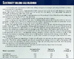
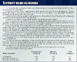
If several wells operate from one utility power meter, the generated electricity from one motor will be used by another motor. The example box illustrates typical electric billing calculations.
Pump cycles
For maximum production from a well, inflow performance relationship papers suggest that the producing bottomhole pressure should not be in excess of 10% of the reservoir pressure.1 12 This means that for timer or POC operations, if the reservoir pressure is 1,000 psi, the producing bottomhole pressure should not exceed 100 psi at the end of the off cycle when liquid has accumulated in the casing annulus.
The bottomhole pressure is the sum of:
- Casing pressure
- Gas column pressure
- Pressure exerted by the liquid column above the formation.
This pressure can be determined with modern acoustic fluid-level instruments that automatically digitize the acoustic data and process casing pressure measurements.13 In most wells, however, reservoir pressure is unknown.
An inexpensive, acoustic, static bottomhole pressure test is satisfactory for determining the maximum producing bottomhole pressure at the end of the shut-in period as a function of reservoir pressure.
Motor start-up
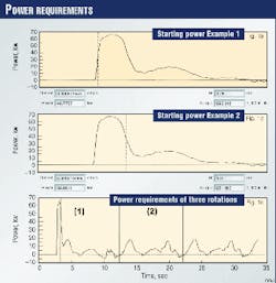
When a motor starts a pumping unit, electrical energy is used to start rotating the counterweights and cranks. Typically, at start-up, a NEMA D motor operates at three times its full load rating for about 0.65 sec in order to power the counterweights and cranks to normal operating speed.
Figs. 1a and 1b show measured power requirements during start-up, while Fig. 1c shows start-up power requirement followed by three rotation cycles with a 30-hp motor.
The energy consumed during start-up is only 0.01 kw-hr, which costs $0.0005. Thus, the consumption charge for starting the 30-hp motor once every 15 min only $1.20/month.
The demand is increased each time the motor is started during any 15-min period. Each start-up/15-min period, for a reasonably loaded motor operating 50% of the time, increases the demand charge by about 1%. Stopping and immediately starting the motor once after each 15-min period affects the electricity bill less than 1%, compared to continuous operations.
An additional electrical demand charge will apply if the total on-off cycle time is less than or greater than 15 min. Heavier, more frequent cyclic loading occurs if the on-off cycle is less than 15 min. But, the average producing bottomhole pressure is maintained at a lower value, which is an advantage. Timers or POCs operating on an on-off cycle in excess of 15 min will increase the demand charge if only a few wells are involved or if all wells start at once.
Longer cycles allow more liquid to accumulate in the casing annulus, restricting liquid inflow. The 15-min on-off cycle is recommended unless other factors are more important than the ones discussed.
Percentage cycle timers
Before installing a percentage cycle timer, pump the well continuously at normal producing conditions until the production rate has stabilized. Then obtain dynamometer surface and pump cards. Precise surface-dynamometer load measurements are not required for calculating a pump card and pump fill.
Because of ease of installation, a qualitative polished-rod transducer is preferable to a quantitative horseshoe load cell. Some pumping units do not need to be shut down for installation of the polished-rod transducer.14
Installation of a horseshoe transducer, which normally requires shutting-down the unit, is more time-consuming and changes the plunger location in the pump. This will also change the formation's producing condition and require restabilization of the production.
To determine the operating time for the pumping unit, multiply the percent fill on the pump card by 1 to 1.1. If the operator prefers the pump completely full at all times, he should use 1.0 times the percentage of pump fill.
For example, if one determines that the pump fill is 25% on the pump card, then the timer should be set to run for 27.5% of the time. This represents a run time of 27.5% of 15 min or 41/8 min. The well is then shut in for 107/8 min before the pumping unit starts again.
The system should produce with a full pump for the first 4 min and then begin to pound liquid due to partial fill. If a full pump is not obtained for about 4 min, the problem should be corrected.
As discussed later, gas interference is the most common cause of inefficient pump operations.
Another method for determining the proper run time involves shutting in the well for about 10 min before starting the pumping unit with a dynamometer monitoring the pump's performance. Monitoring continues for as long as the pump is full of liquid.
One should note the run time before the pump begins to "pound" liquid because of partial fill. The percent of time that the pumping system should operate is the run time divided by the 10 min shut-in period plus the run time.
Another technique for determining the approximate percentage timer setting is to determine the fraction of run time that a pump should be operated by dividing the well's production by the predicted pump capacity. This procedure assumes that the pump is filled with liquid on the up stroke and that the pump is operating efficiently.
QROD is a free, simple wave-equation predictive beam pump program for estimating pump capacity and pumping unit loadings that can be downloaded from the internet site, www.echometer.com.
Pump fill should be verified with a dynamometer pump card, if possible. All practical methods available should be used to optimize the timer setting, including visual observations.
Periodic checks are recommended to maintain the proper run-time setting. Many pumping units that produce low volumes of liquid operate in the 6-7 spm range. This results in about 100 strokes/15-min period. Thus, a 15-min percentage timer approximately indicates on the dial the number of strokes that will be obtained during the 15-min period.
If the pumping system obtains full pump cards for 25 strokes and then obtains 10 strokes of partial pump fill, the operator would probably desire to reduce the run time slightly. If the timer were set at 30% run time, reducing the run time by 5% would stop the pump from operating during the last five partially filled pump strokes (approximately) and improve efficiency.
Dynamometers offer the most precision for properly setting the percentage cycle timers. An operator may observe the behavior of the polished rod to estimate the pump fill. Complete pump fill, however, is often difficult to determine by observation, and for efficient operations, it is important that the pump fill is near 100% throughout most of the pump on cycle.
The consumption of power should be measured at full pump fill and the overall system efficiency determined so that it is between 40 and 60%.12 15 16
One should confirm having a full pump until pump cards show partial fill that approximates the fill observed when the well operates continuously. Also, one should confirm that at the end of the pumping on cycle, the liquid level in the well bore is at the pump. This ensures maximum production.
Cost savings
In the beam system, moderate pumping speed with moderate loading on the equipment will result in better power efficiency than with lightly loaded equipment. The pumping unit should use a long stroke. One should install a timer or POC if the moderately loaded pumping system pump capacity exceeds the well's production.
Gas interference in the pump is the most common contributor to low efficiency. To alleviate this, one should set the pump intake below the formation and use a single tube below the seating nipple, or use an efficient downhole gas separator if the pump is placed at or above the formation.17
For pumps set at or above the formation, one should use an efficient downhole gas-liquid separator with a large, thin-wall outer barrel, large inflow ports, and proper dip-tube design. A back-pressure valve on the tubing discharge wastes electricity and increases maintenance requirements.
Free gas should be separated from the liquid downhole before the liquid enters the pump so that excessive free gas is not present at the surface to cause stuffing box lubrication problems. A 300-psi back-pressure on the tubing in a 4,000 ft well will increase the electricity bill by about 15% and will cause additional rod loading, additional gear-box loading, and less plunger travel.
Timer application
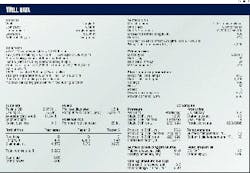
A POC was installed on Cobra Oil and Gas Corp.'s Rvogta 8 well, in Wichita County, Tex. The system did not perform properly because the pump fill was very erratic due to gas interference. Table 1 shows the data used by Echometer Co., Wichita Falls, Tex., to analyze the well.
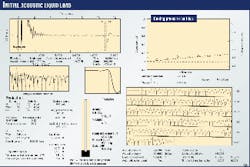
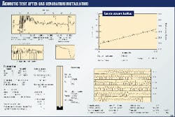
An acoustic liquid level depth measurement indicated the liquid level to be 148 ft above the pump when the well was producing at stabilized conditions. The casing pressure increased by about 0.1 psi/min when the casing valves were closed, which indicated that free gas was being produced from the formation and was flowing up through the annular liquid (Fig. 2).
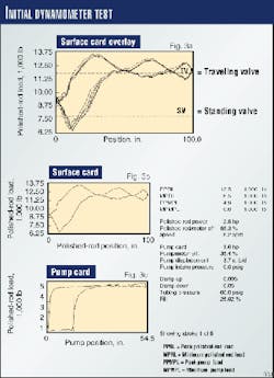
To determine stabilized pumping conditions, a dynamometer test was run without the pumping unit being shut down (Fig. 3). The analysis showed that the pump fill was 27%. Traveling and standing valve tests indicated that the pump was in good condition. When a high liquid level is present above the pump and the pump does not fill with liquid on the upstroke, poor downhole gas separation exists.
The pump was set above the producing formation, at 5,173 ft. The well produced from the 43/4-in. open hole between 5,235 and 5,247 ft.
The acoustic and dynamometer data indicated that the "poor boy" gas separator was inefficient, as is often the case.
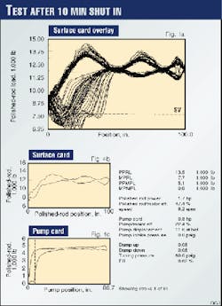
After the well was shut in for 10 min and then restarted, low pump fill occurred even after the well had been shut in for 10 min (Fig. 4). The well was tested again after being shut in for 20 min. Again, a dynamometer test indicated low pump fill and another acoustic test showed the liquid level to be high, indicating an inefficient downhole gas separator.
Cobra decided to improve efficiency by installing a better gas separator and a timer to control the pumping unit's operating time.
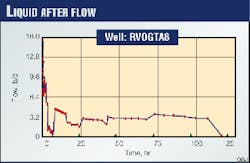
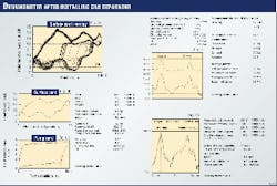
The producing bottomhole pressure was about 94 psi, and to obtain a reservoir pressure, Cobra shut-in the well for 5 days. The buildup (Fig. 5, at right) shows that the well pressure did not stabilize, although it does indicate a reservoir pressure (P*) exceeding 1,000 psi. The analysis also indicates that the reservoir has a low skin factor and permeability. Liquid flow into the well bore after shut-in was about 10 b/d (Fig. 6, below right).
These build-up data indicate that very little additional production will be obtained after correcting the gas interference problems. The main benefits of better gas separation and a timer will be reduced electrical costs, less maintenance due to less run time, and better equipment loadings.
The low liquid flow indicates that some cross-flow is occurring in the formation, and probably, the pump should be set as low as possible.
The pump, after being pulled, required the pull tube to be replaced. The worn pull tube was probably the result of continuous "pounding" of the pump plunger when the pump was 20-50% filled with liquid. The pump also had two standing valves.
Only one standing valve was included when the pump was rerun. A tubing anchor was in the well when it was pulled, but the tubing anchor had a broken spring and was not rerun. The tubing string consists of 167 joints of 23/8-in. tubing, a seating nipple, and a 23/8-in., 6-ft long collar-size gas separator.
The bottom of the gas separator was placed 3 ft above the TD, in the middle of the producing formation.
After the well was pumped overnight, the liquid level was tested and found to be at the seating nipple, 166.88 joints from the surface (Fig. 7).
A dynamometer card and well test without shutting down the pumping unit indicated about 30% pump fill. With the liquid level at the pump and partial pump fill occurring, the gas separator was operating efficiently.
After the well was shut-in for 9 min, the pump was restarted for about 10 min. The first 36 strokes indicated full pump fill. The next seven strokes indicated the well was being pumped down, and from stroke 43 to the final stroke 60, the pump fill was relatively stable, about 35% (Fig. 8).
Installation of the collar-size gas separator was successful. A percentage 15-min cycle timer was installed and set to run 33% of the time.
Before installation of the timer and gas separator, the well produced 8.2 bo/d, 35 bw/d, and 4 Mcfd of gas. With continuous production, electricity bills were about $203/month. After installation of the gas separator and timer, the oil, water and gas production rates increased slightly, as was expected, and the electricity bill decreased to $108/month.
The beam pump system now operates 5 min on and 10 min off with a full pump during most of the on time. The operation is smoother and, hopefully, the next downhole maintenance requirement will be at least three times further in the future.
Cobra's changes will payout in 8 months, based on the reduction in electricity cost and an estimated reduction in maintenance cost due to better equipment loading and 33% run time. The overall electrical efficiency was improved to 59% from 35%.
Acknowledgment
The authors appreciate the help of Cobra Oil & Gas Corp. personnel in the preparation of the article.
References
- McCoy, J.N., Podio, A.L., and Huddleston K.L., "Analyzing Well Performance XV," Artificial Lift Workshop, April 1987.
- Lea, J.F., "New Pump-Off Controls Improve Performance," Petroleum Engineer International, December 1986.
- Westerman, G.W., "Successful Application of Pump-Off Controllers," Paper No. SPE6853, October 1977.
- Dunham, C.L., "Supervisory Control of Beam Pumping Wells," Paper No. SPE16216, March 1987.
- Gill, R.A., Soza, R.L., and Ott, R.E., "Using Pump-Off Controllers (P.O.C) To Their Fullest," Southwestern Petroleum Short Course, April 1997.
- Neely, A.B., and Tolbert, H.O., "Experience with Pumpoff Control in the Permian Basin," Paper No. SPE14345, September 1985.
- Jentsch Jr., W.A., and Marrs, R.D., "Computerized Automation of Oilfield Production Operations," Paper No. SPE15392, October 1986.
- Gibbs, S.G., "Utility of Motor Speed Measurements in Pumping Well Analysis and Control," Paper No. SPE13198, September 1984.
- U.S. Patents, 4,286,925; 4,307,395; 4,594,665; 4,487,061; 4,793,178; 4,509,365; 4,483,188; 4,551,730, 4,509,901, 4,583,915, 3,838,597; 3,817,094; 4,583,915; 4,509,365; 4,058,757 and numerous others.
- From www.thomasregister.com/olc/cramer (electrical/mechanical interval and percentage timers)
- From www.ssac.com (inexpensive solid-state percentage timer)
- Vogel, J.V., "Inflow Performance Relationships for Solution-Gas Drive Wells," Paper No. SPE1476.
- McCoy, J.N., Podio, A.L., Drake, B., and Becker, D., "Total Well Management A Methodology for Maximizing Oil Production and Minimizing Operating Costs," SPE Third Annual Symposium, May 1995.
- McCoy, J.N., Jennings, J.W., and Podio, A.L., "Polished Rod Transducer for Quick and Easy Dynagraphs," Southwestern Petroleum Short Course, April 1992.
- Lea, J.F., Rowlan, Lynn, McCoy, J.N., "Artificial Lift Power Efficiency," Southwestern Petroleum Short Course, April, 1999.
- McCoy, J.N., Podio, A.L., Ott, R., and Woods, M., "Electrical Motor Power Measurement as the Key for Optimized Rod Pumping," Paper No. SPE 36080, April 1996.
- McCoy, J.N., and Podio, A.L., "Improved Downhole Gas Separators," Southwestern Petroleum Short Course, April 1998.
The Authors
James McCoy has been the owner of Echometer Co., Wichita Falls, Tex., since 1962. The company sells acoustic liquid level instruments and a well analyzer system. McCoy has a BS in petroleum engineering from the University of Oklahoma and an MS in petroleum and natural gas engineering from Penn State University.
A.L. Podio is holder of the H.B. Harkins professorship in petroleum engineering at the University of Texas, Austin. His teaching and research interests are primarily in the areas of drilling and production.
Dieter Becker is involved in research and development for Echometer Co., Wichita Falls, Tex. Before joining Echometer in 1990, he worked for Gulf Oil and Chevron Corp. as a production and reservoir engineer. Becker holds a BS in geological engineering from the University of Missouri-Rolla.
