Multiphase pumps offer alternative for moving wellhead fluids
Multiphase pumps are starting to provide an alternative for moving fluids from producing wells to a centralized production facility.
Installation of these pumps can reduce capital costs as illustrated by a project completed by Mobil Oil Canada in one of its Alberta oil fields.
Multiphase pumps often are installed to:
- Reduce back pressure on oil and gas wells, thereby increasing producing rates.
- Boost pressure between an oil and gas field and central processing facility.
- Boost pressure at a gas processing facility where liquids are present.
Mobil's facility
In 1997, Mobil Oil installed a twin-screw multiphase pump package in one of its oil and gas fields in Alberta. The project aimed to increase producing rates for both oil and solution gas from several wells, as well as to increase ultimate recovery.
Before deciding to install multiphase pumps, Mobil evaluated other technologies such as conventional compressor facilities. The evaluation determined that the multiphase pumps appeared to have the lowest estimated capital installed costs.
The project design called for installing two twin-screw multiphase pumps (in parallel) at a satellite (junction) to handle flow from eight wells, producing at a rate of 18.3 MMcfd of gas, 1,250 bo/d, and 9,050 bw/d at suction conditions.
For proper pump performance, the design included external water recirculation to ensure sufficient liquids at the pump suction.
Two pumps in parallel were installed because no single pump was found that could handle the volume of gas, oil, and water at the conditions required.
Finally, the design included electric motors with variable frequency drives (VFD) that allowed for additional control flexibility.
Project development
Facility project design and execution encompasses a series of stages from "idea" through to post-project assessment. These stages usually include:
- Idea development
- Scoping evaluation
- Technical study approval
- Front-end engineering
- Authority for expenditure (AFE) approval
- Detailed engineering
- Procurement
- Construction
- Commissioning and start-up
- Post-project assessment.
The following describes how these stages were applied in the Mobil Oil facility.
Idea development
About April 1997, Mobil had an ongoing drive to increase oil and gas production from new and existing wells throughout the Western Canadian basin. Among the alternatives listed was the possibility of installing multiphase pumps for reducing tubing head pressure (THP) to help stimulate production from existing wells.
After potential sites were identified, the sites were evaluated in the next stage.
Scoping evaluation
For the scoping evaluation, Mobil gathered production records, historical data, IPR (inflow performance relationship) data, and decline-rate data for a number of well sites. Mobil then determined the projected production boost based on the difference between current THPs and projected THPs.
The data indicated that many wells did not show a significant boost in oil and gas production due to a change in THP. Thus, these wells were dropped from further evaluation.
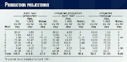
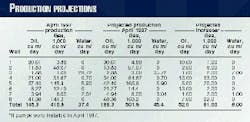
Eight wells, all in the same reservoir, showed promise for increased production after lowering THP by about 145 psig (Table 1). The projected increase applies to only April 1997 and did not take into account the 20% production decline rate of the reservoir.
The multiphase pumps were commissioned in June 1998. At that time, after accounting for the decline rate, Mobil projected the increase in oil and gas production to be 40.5 cu m/d and 71,000 cu m/d (255 bo/d and 2.5 MMcfd), respectively.
The field gathering system required detailed technical and economic evaluations to determine how to reduce the THPs at each well by at least 145 psig and the costs associated with this change.
Installation of individual multiphase pumps at each well site could attain the required THP, but the cost of eight separate multiphase pump installations was prohibitive. Compressors at each well site with liquids-handling capability could also reduce the THP; this option again was cost prohibitive, however.
A multiphase pipeline and gathering system computer simulation was used to determine the pressure drop from each well to a central satellite production facility. The objective was to reduce the THP at each well while minimizing the size of the multiphase pump at the central satellite.
Variables evaluated included pipeline diameter, length, terrain, production rate, temperature, viscosity, etc.
From the evaluation, Well No. 2 (Table 1) was selected as the central site for one multiphase pump installation that could decrease the THP of all eight wells by 145 psig. This site required a multiphase pump that could maintain a suction pressure of about 116 psig.
A conventional compressor installation with liquids-handling capability was also evaluated for the central site. But, the multiphase pump facility projected costs were less, based on historical cost data. The lower cost of multiphase pumps was mainly attributed to the elimination of auxiliary equipment, typical in most conventional systems.
The Mobil multiphase pump project did not include the technical study approval and front-end engineering stages because the project was not considered sufficiently large for further front-end development.
The project proceeded with the multiphase pump after Mobil and its partners approved the AFEs.
Engineering, procurement
The detailed design of the Mobil facility involved a team from four engineering disciplines: mechanical, process, civil, and electrical-instrumentation.
A large portion of the detailed design, involved correctly applying multiphase pumps and drivers based on the conditions provided in the scoping evaluation stage. Finalized drawings and specifications were developed at this stage.
The project was completed in a "fast-track" mode, which essentially means that material is procured side by side during the detailed engineering phase. Although fast-tracking all projects is not recommended, fast-tracking is often required because of business reasons such as schedule or long equipment-delivery constraints.
The engineering-procurement phase for the Mobil facility took about 4.5 months.
Construction, start-up
A construction kick-off meeting, with contractors, was held on Apr. 8, 1998. The meeting covered all construction packages that included drawings and specifications and finalized the schedule for each contractor. The meeting also addressed issues concerning construction management, quality, and site safety.
Overlapping of contractors was a concern because site worker density could affect the schedule. The construction phase went smoothly, however, lasting about 2 months without major delays.
Commissioning and start-up on this project lasted about 1 week. Most of the time was spent on operator training, mechanical completions, electrical completions, and prestart-up testing. No major problems were encountered.
Post-project assessment
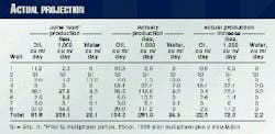
About 3 months after start-up, the facility was evaluated. Well tests determined that the actual increase in production based on the reduced THPs at each well (Table 2) was close to the projected increase (Table 1).
The actual production increase in Table 2 is a differential between September 1998 production (after multiphase pump start-up) and June 1998 production (before multiphase pump start-up). If one allows for an annual 20% reservoir decline rate, the actual increase in production for oil and gas for June 1998 changes to 27.5 cu m/d and 84,900 cu m/d (173 bo/d and 3.0 MMscfd), respectively.
A comparison of actual to projected production increases and accounting for decline rates show that the actual oil production was 13 cu m/d less than projected. Actual gas, however, was 13,900 cu m/d more than projected. Re-evaluation of the project economics based on actual production changes and capital investment, proved that this was a successful project.
Since start-up, the single, mechanical, metal bellows seals with two hard faces (silicon carbide vs. silicon carbide) have had a mean time between failures of 1 week to 4 months. The metal bellows seals had a tendency to fatigue in gas or light hydrocarbon liquid.
Thus, a new seal arrangement has been installed that consists of a pusher-type single spring with a soft rotating face (carbon) and a hard stationary face (silicon carbide). The initial results have been promising.
Multiphase pumps
Multiphase pumps can be successfully installed for many different applications in the oil and gas industry. The Mobil project was successful from the idea stage through to the post-project assessment stage. Except for the mechanical seals, no changes have been made to the facility since start-up.
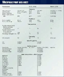
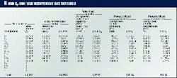
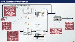
The data sheet (Table 3) contains information that is usually required before multiphase pumps can be correctly installed. Recent field values (March 1999) from the Mobil installation have been inserted for reference. Fig. 1 shows the basic flow diagram of the Mobil installation.
Gas volume fraction
Once all the data have been collected, the next step is to determine the gas volume fraction (GVF) based on suction conditions.
Most twin-screw multiphase pump manufacturers limit the GVF based on suction conditions to a maximum of 97%. If the GVF is higher than 97%, an alternative source of liquid must be added, such as recirculation, to ensure an appropriate GVF. Equation 1 (see equation box [pdf format]) defines GVF.
The example box illustrates the calculations with data from the Mobil facility (Table 3).
Twin-screw multiphase pumps to operate effectively generally require a minimum amount of liquid at the pump suction. The liquid is necessary to maintain a proper seal between the screw clearances and also to maintain lubrication and cooling for the mechanical seals.
As previously discussed, the minimum liquid amount is based on a maximum GVF of 97% for most multiphase pumps. The GVF calculated in the example box is too high. Thus, reducing the GVF will require incorporating a liquid recirculation system that will decrease the GVF to a more appropriate level.
As Table 3 shows, including a water recirculation rate of 264 gpm will change the GVF to below 97%. Also, since the suction temperature increases to 144° F. just downstream of where the recirculation loop is tied in (Table 3), the actual gas flow rate increases to 1,726,759 from 1,535,215 cfd.
It is important to note that a cooler is unnecessary because of the continual flow of cool liquid from the wells, with the loss of hot liquid downstream to the pipeline. This maintains an acceptable operating temperature in the recirculating liquid system after reaching almost steady-state conditions.
Thus, the after recirculation GVF at pump suction is 96.9% (see example box [pdf format]).
Efficiency, horsepower
Currently, most multiphase pump manufacturers are using hydraulic liquid pump equations to determine overall pump efficiency. The following discussion, however, will show that using hydraulic equations is not an accurate method for determining overall multiphase pump efficiency and horsepower when gas is involved.
Overall pump efficiency for hydraulics is shown by Equations 2 and 3.
Hydraulic horsepower (or hydraulic kilowatts in metric units) for pumps is developed from the Bernoulli energy conservation equation (Equation 5).
The Bernoulli equation has three basic assumptions before it can be applied correctly:
- Incompressible fluid p = constant)
- No fluid friction
- Negligible thermal energy changes.
Assuming kinetic and potential energy across the pump is negligible (as it usually is), then Bernoulli's equation reduces to Equation 6.
Various forms of HHP or HKW have been developed depending on the units used for DP and Q. The most common forms are shown as Equations 7 and 8.
Mobil facility horsepower
Most multiphase pump manufacturers, unfortunately, are using HHP or HKW equations to determine the actual hydraulic horsepower of a multiphase pump. They generally use the total actual mixed flow rate (including gas based on suction conditions) and substitute it with Qactual in the HHP equation. This will over estimate actual hydraulic horsepower because gas is included and treated as a liquid.
The calculation under the horsepower section in the example box is based on data from Table 3 and results in a gas isentropic horsepower of 634.5 hp, which is a much greater than the horsepower calculated in the gas isentropic section in the example box. This difference is due to the gas being treated as a liquid in the horsepower section.
Multiphase pump manufacturers calculate horsepower in this manner for one reason only: to protect against the possibility of a 100% liquid slug passing through the pump. As a result, this becomes very costly because greater horsepower drivers are required just in case of a liquid slug. Under normal operations, however, the pumps typically would be underloaded.
Many, less costly ways of getting around liquid slugging include:
- Introducing an upstream slug catcher
- Reducing the pump speed when a slug is detected upstream to avoid excessive torque
- Having a control philosophy that a VFD operated pump/motor can be a function of load. In this case, the pump driver speed will ramp up or down based on maintaining a constant load.
Thermodynamics
The recommended method to determine horsepower is to model a multiphase pump as a liquid pump and a gas compressor operating in parallel with the same suction/discharge temperature and pressure after mixing (Fig. 2). The ideal horsepower requirements are then determined from a thermodynamic point of view, which is applicable when two or more phases are present in a single application.
With this model, one assumes an isentropic (reversible adiabatic) steady-flow system. Most compressor manufactures use the isentropic steady-flow system when evaluating power under ideal situations (no efficiency losses). The steady-flow energy equation (SFEE) takes the form of Equation 9.
For most installations, the discharge and suction nozzles are both at the same relative elevation and have the same size. Thus, the kinetic and potential energy changes across the pump are negligible.
Also, one can assume an isentropic process, which is defined as no net heat gain or loss to or from the system and the entropy (DS) from suction to discharge remains constant. Neglecting sign notation, the SFEE can be reduced to Equation 10.
In Equation 10, Dh is the change in the system enthalpy or in the case of a pump or compressor, it is the change in enthalpy from suction to discharge.
With the model having a pump and compressor in parallel and using the current data from Table 3, one can determine the work done by both pump and compressor.
Liquid isentropic horsepower
If one assumes the internal energy in a liquid pump changes very little from suction to discharge, the value DU can be assumed to be 0. Also, because most liquids are only slightly compressible, the specific volume or density is assumed constant from suction to discharge, thus V = constant.
The change in enthalpy from suction to discharge in a liquid pump can be expressed by Equation 11.
Note that in Table 3 most of the liquid, including that being recirculated, is water. Saturated steam tables will show that the specific volume of the water at 144° F. is about 0.01632 cu ft/lbm. Thus, for the Mobil facility Dh = 0.3548 BTU and the Pshaft = 19.64 hp (see example box).
Note that the assumption that all liquid flowing through the pump is water results in determining the greatest horsepower requirements. In fact, however, 524.2 bbl of oil are flowing through the pump, a small volume compared to total volume of water flowing through the pump. Therefore, the change in horsepower requirements, if oil is included, is minimal.
Also important to note is that Bernoulli's conservation of energy equation for determining the actual hydraulic horsepower requirements of the liquid portion will give an identical result.
Gas isentropic horsepower
Unlike a liquid pump, the specific volume (density) of a gas will not remain constant because it is being compressed from the suction to the discharge. As a result, Equation 12 has been developed for isentropic steady-flow systems when gas behaves according to the ideal gas laws.
A gas will behave similar to an ideal gas if its pressure is low compared to its critical pressure and the temperature is much greater than its critical temperature. In other words, the compressibility (Z) of a gas should be equal to 1.0 in order to assume ideal gas.
For ideal gases, changes in thermodynamic properties (from suction to discharge) such as enthalpy can be found directly without knowing the initial (suction) and final (discharge) property values.
One can correct the ideal gas equation to compensate for the compressibility factor (Z) by calculating an average compressibility factor between suction and discharge. Therefore, the change in enthalpy across a compressor according to ideal gas laws (making provision for compressibility of a real gas) for an isentropic steady-flow system is expressed as Equation 12.
The determination of cp and k of a gas mixture requires calculating both the molecular weight (MW) and cp based on the mole fraction of the individual components. Table 4 illustrates this procedure.
The Zave is determined from compressibility charts using pressure/critical pressure ratios and temperature/critical temperature ratios.
An example for these calculations is shown in the example box section "Gas isentropic horsepower." The determination of both cp and k uses data from Table 4.
The total isentropic horsepower simply becomes the addition of total liquid isentropic horsepower and total gas isentropic horsepower. Thus, for the Mobil facility, this equals 455.6 hp.
Efficiencies
Total isentropic horsepower excludes adiabatic (isentropic) and mechanical efficiencies which are used to determine the BHP or BKW (Equation 13).
Gas horsepower (GHP) is a common term in the compression industry, which does not include mechanical efficiency losses. GHP can be obtained with Equation 14.
The Mobil field facility based on the conditions in Table 3 has a known total load, on average, of about 898 hp. This load includes lights, VFD, vent fans, air compressor, and heaters.
The multiphase pump BHP is about 804 hp, because the motors and the VFD both have about 95% mechanical efficiency and the power consumed by the lights, blower motors, air compressor, vent fans, and heaters is subtracted out. Thus, the overall efficiency is 57%.
With a 90% mechanical efficiency of the pumps, the adiabatic efficiency is about 63%. These efficiencies are much higher than what is usually quoted from most multiphase pump manufacturers.
It should be noted that twin-screw multiphase pumps actually operate at higher total efficiencies than that normally reported. Thus, the drivers (motors) are actually being oversized in most applications. This can impact installed cost.
Energy, material, equilibrium
Before a facility is installed (Fig. 1), it is difficult to estimate the after recirculation suction temperature and the mixed (phases) discharge temperature with hand calculations. The calculations require the initial and final hydrocarbon enthalpies to be determined from hydrocarbon enthalpy tables.
Until the suction and discharge enthalpies are known, the subsequent temperatures cannot be found. It is therefore recommended to use a thermodynamic energy/material/equilibrium balance simulation computer program that is specifically designed for the oil and gas industry.
If the program is equipped with a graphical interface, then process flow diagrams, such as Figs. 1 and 2, can be input along with the process conditions such as in Table 1.
Two excellent program simulators designed for the oil and gas industry are "Hysis" and "Chemcad."
For the Mobil facility, in Table 3, the after recirculation suction temperature of 144° F. and the discharge temperature of 162° F. are actual field values. A computer program simulator, however, will provide values that are close to actual. Therefore, determining whether or not a recirculation cooler is necessary for a proposed facility, can be accurately found prior to installation.
Acknowledgments
The information contained in this article would not have been published without the full cooperation of the operations and maintenance staff at Mobil Oil Canada, the engineering team at Optima Engineers & Constructors and the design group at Bornemann Pumps.
References
- Compressors and Expanders, Gas Processors Suppliers Association, 10th Edition, 1987.
- Pumps and Compressors, Marks Standard Handbook for Mechanical Engineers, 8th Edition, 1978.
- Dal Porto, D.F., and Larson, L.A., "Multiphase-Pump Field Trials Demonstrate Practical Applications for the Technology," SPE Production & Facilities, August 1997.
The Author
Glen T. Wyborn is a project engineer with Optima Engineers & Constructors Inc., Calgary. He has worked with twin-screw, multiphase pumps for several years. Wyborn has a BS in mechanical engineering from the Montana State University, Bozeman, Mont.
