DP drillships target deepwater operations
After a 10-year construction hiatus, contractors began delivering a series of next-generation drillships last year, fulfilling a need for technically advanced, deepwater drilling rigs.
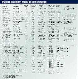
Each of the 16 new drillships (Table 1), the last to be delivered in December 2000, will use a combination of dynamic-positioning (DP), riser tensioning, and motion-compensating systems to neutralize the effects of wind, waves, and currents.
This conclusion of a two-part series (Part 1, OGJ, May 3, 1999, p. 69) focuses on technologies that:
- Keep the rig from drifting away from the well center
- Avoid riser buckling
- Stabilize the drillstring from up-and-down movements.
Dynamic positioning
Offshore drilling contractors use two methods to stay on location-mooring and DP. In deepwater environments, however, anchor-mooring systems do not provide a practical means for station keeping.
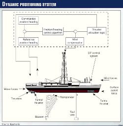
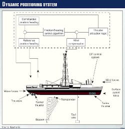
Instead, companies opt for DP technologies that combine computer, positioning sensors, and telecommunication technologies to actuate thrusters positioned along the vessel (Fig. 1).
ABS classification
The American Bureau of Shipping's (ABS) DP classification system provides a framework for vessel design, most useful in describing DP technology. This system, as follows, depends on the degree of redundancy and sophistication built into the drillship:
- DPS-0: No backup DP system on board
- DPS-1: Manual centralized control backup, automatic heading
- DPS-2: Backup for any single fault
- DPS-3: Backup for combination of any single fault and one-compartment loss.
Although the ABS system has become an industry standard, by no means does it regulate the selection process for vessel design. Instead, this is left to the contractor, with system design typically depending on whether the ship is an upgrade or new build.
DPS-0 and 1
To achieve a DPS-0 rating, the vessel requires a centralized manual control system and automatic heading control. In this case, the ship uses information from one position reference system, one wind sensor, and one gyro compass.
These systems must be located at a main DP control station where the operator is aware of the external environmental conditions and any activities relevant to the DP operation.1
No redundancy is required with DPS-0, and applications typically involve operations in which the DP function does not endanger human lives or may cause major damage in case of failure.
If there is a chance that loss of position will result in some pollution and minor economic damage, excluding harm to people, vessel operators typically implement a DPS-1 system.2 Again, this system does not require comprehensive redundancy.
Instead, the manual position and auto heading control system must provide backup for the fully automatic system, which in turn has sensor redundancy and a more-secure power supply. Position-reference sensors, wind sensors, and gyros are provided in duplicate.
DPS-2 and 3
If a loss of position can create consequences of severe pollution, significant economic damage, and accidents to people, an operator will build a DPS-2 drillship. And if position loss may result in severe pollution or fatal accidents, a DPS-3 system should be used.
Both systems include a power-management system that automatically ensures sufficient power for essential operations. Furthermore, DPS-2 and 3 systems use a consequence analyzer for the continuous monitoring of thrust and to maintain heading and position under prevailing environmental conditions. The analyzer also calculates thrust capability in the event of a single failure.
In relation to DPS-2, a DPS-3 vessel requires:
- An additional backup control station, including a third automatic heading and position control system
- A third gyrocompass fitted in the backup control station
- Independent and uninterruptible power supplies (UPS) for the backup system, position-reference system, and gyro compass.
For a DPS-3 vessel, the backup control station must be situated in a separate compartment, sited and arranged so that no single fault, including fire or flood in one compartment, will render both main and backup control systems inoperable.1
Additionally, generators and distribution systems must be sized and arranged in at least two compartments. Thus, if the vessel loses any compartment, sufficient power will remain available to provide essential system loads.
DP class selection
"Of the three classes for DP systems, only two are viable for a drilling vessel: DPS-2 and DPS-3," said Chuck Sims, electronics system supervisor for Global Marine, at the Marine Technology Society's Dynamic Positioning Conference last October. For conversions, Sims says the design of the original vessel dictates system choice.
For example, "When we converted the Glomar Celtic Sea from an accommodation to a drilling vessel, we had a DPS-3 platform to begin with, so the choice to maintain this class through construction was obvious and brought with it no significant additional costs."
The Glomar Explorer, on the other hand, was originally built with a redundant DPS-2 system in a generation where there was no thought of DPS-3, he explained. To obtain a DPS-3 classification, Global Marine would have needed to address compartmentation, cabling, piping, and tankage issues.
This was "simply not feasible within the (economic) boundaries of the project," Sims said. Instead, Global Marine performed minor modifications to reduce exposure to DPS-3 type events while considering DPS-3 issues for new systems and equipment.
When it comes to DP selection for new builds, however, the operator plays an important role in system selection. In these cases, E&P companies hold long-term contracts with the drilling contractor, resulting in team-oriented work environments.
For example, class determination for Global Marine's new-build "Hull 456" drillships, including the C.R. Luigs and Jack Ryan, evolved partly through the needs of BHP and Exxon Corp.
Be aware
Although these advanced systems provide redundancies designed to avoid mishaps and minimize downtime, Sims pointed out that "DPS-3 classification does not, nor can anything else, make a catastrophic disconnect scenario impossible." Instead, "it can only reduce the risk of such a happening."
Software reliability and software fault-tolerance issues also concern Sims, perhaps more so than hardware. "We can put together a triple-redundant system, yet the software is identical in every machine. We probably have a software package which is, at least in part, a Beta test version at best. That means that we have, in the best systems, a possibility of single point failure locations," he said.
Thrusters
"A primary concern when designing a DP vessel is how much downtime the rig will experience with thruster repairs and how much up time can the rig experience during harsh weather," said Mark Dreith, senior manager of marine projects for Global Marine.
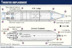
Thrusters play an essential role in DP design, varying from ship to ship (Fig. 2). For example, the Glomar Explorer employs five tunnel thrusters; four fully azimuthing, retractable thrusters; and two main propellers, providing 35,200 hp of thrust. In contrast, the C.R. Luigs maintains station exclusively with six retractable, fully azimuthing thrusters, providing 40,200 hp of thrust.
"Whereas azimuthing thrusters can be rotated, tunnel thrusters are fixed into the bow and stern," explained George Smith, senior DP officer for the Glomar Explorer.
"You can vary the amount of thrust on (a tunnel thruster) to move the heading around, but it can only thrust port and starboard. Of course, if you apply more power, you can (adjust) the yaw, but they won't spin 360° like azimuthing thrusters can." The same holds with the main props, which are also fixed.
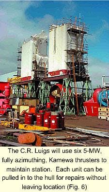
On the C.R. Luigs and Jack Ryan new builds, "The vessels are divided in half," Dreith explained. Two thrusters are located on the stern (Figs. 2, 5, and 6), two forward (2 and 3), one aft centerline (4), and one on the bow on centerline (1).
Thrusters 1 and 4, located along centerline, can be flexibly controlled from either engine room, depending on the need. The remaining thrusters, however, are tied to specific engines. For example, the starboard engines control starboard Thrusters 2 and 5 while the port engines control port Thrusters 3 and 6.
This type of configuration allows the vessel operator to stay operational under a variety of conditions. "If you take a look at a typical 10-year Gulf of Mexico (GOM) loop current, with 32-knot winds, significant waves (11.8 ft), and a 3.2-knot current, we would only use 5 MW (6,700 hp) of power to stay on location if the vessel (C.R. Luigs) faced these forces directly," Dreith said.
And if concurrent environmental forces swing around and hit the vessel directly on the beam, it would only require 20 MW of thrust (26,800 hp) to hold the vessel against that force, leaving us with 10 MW to spare."
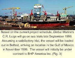
Engineers calculate the C.R. Luigs will easily maintain station even in a GOM 50-year storm (Fig. 3), with the long-axis turned 90° to unidirectional environmental conditions.3 And with one thruster down, the vessel will still be able to stay on location, as long as it is partially weathervaned (40° off the bow).
A squall
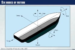
The ability of a vessel to weathervane-or turn the ship's bow in the direction of oncoming wind, waves, or currents-extends the operational window of drilling operations. A vessel's position depends on six modes of motion: heave, pitch, roll, surge, sway, and yaw (Fig. 4). To maintain position, however, DP navigators concentrate on surge, sway, and yaw; otherwise the ship will drift.1
Earlier this year, the Glomar Explorer displayed its ability to maintain operations during rough weather, clearly showing that proper thruster configuration and power output can maintain station keeping with little or no down time. This is extremely important for deepwater operations with day rates on the order of $200,000/day.
"We were facing south last hitch," Smith said, "when a squall overcame us." As the front passed through, almost immediately and within seconds, it came up to the west, with a 60-knot wind hitting the vessel directly on the beam.
"We changed heading towards the wind, but it continued to shift. And by the time we came around, we were looking at an 83-knot wind on the bow," he said. As the drillship made the heading change, "we stopped the vessel half way through so as not to overcompensate for the heading changing."
Nevertheless, "The vessel came up and in fact went past the mark," demonstrating the power of the thrusters. Thus, "We not only held with a 65-knot beam wind but we also held stationary with a 100-mph wind on the bow."
Smith said during these station-keeping maneuvers, operations continued. "We were up wind only 114 ft, well within the safety margin (of 469 ft) before it becomes necessary to disconnect. There was only about 1° on the riser at a water depth of 5,000 ft."
Additionally, the vessel has a well-placed center of gravity, making it difficult to roll or pitch (Fig. 4). "When that squall hit us, it hit us right now, and all we took was a 1.4° list," said Louis Solana, captain of the Glomar Explorer.
Contributing factors for a capable drillship include structural makeup, derrick placement, and beam width (116 ft). "Because the (Glomar Explorer) was purpose built for the U.S. Navy,4 the steel in it is fantastic. For example, the main deck steel is 2 in. in places, much more than any other drillship out there today."
And "You can feel (the stability) in the way the ship moves, it rolls very quickly," Solana said.
Thruster bias
The maneuverability of the Glomar Explorer, and other vessels like her, depends on the amount of counteracting force constantly directed from one thruster to another. Otherwise known as bias, offsetting thrust plays an important role in a vessel's instantaneous ability to turn and thrust.
"Bias has two functions," Smith said. First, it provides readily available operating power, particularly important for "instantaneous" movements. Thus, by maintaining a constant load on the power plant, when it comes time to move the ship, it simply becomes a matter of turning the thruster's azimuth. "We typically maintain 35% bias on the Glomar Explorer," he said.
On the other hand, if the thrusters remain unbiased, it then becomes necessary to ramp up idling engines, resulting in additional time needed to correct the vessel's position.
"Second, bias stops the thrusters from hunting. If they have nothing to push against, they tend to spin around," Smith added. Therefore, if the vessel requires a position correction, reaction time will be compromised because the thrusters, perhaps off by 180°, will have to swing around.
Serviceability
Traditionally, thruster repair and maintenance activities force vessel operators to perform repair work in protected waters, requiring the assistance of divers, cranes, and anchor-handling vessels.5 And while all DP vessels can maintain station in limited weather with an inoperable thruster, it is not practical to keel haul a down thruster while deploying divers.3
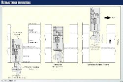
To resolve this issue, Global Marine designed azimuthing thrusters that can be pulled vertically into the ship. "We've mounted our (azimuthing) thrusters in a retractable canister (Figs. 5 and 6), thus, we can work on them from inside the hull," Dreith explained.
This retractable feature allows crew members to pull up within the thruster well, above the operating draft, instead of from outside the ship. "We can actually pull the propeller and change seals while operating."
Although the Glomar Explorer and 456 Hulls utilize retractable thrusters, both designs use different mechanisms to pull the thruster into the hull. The Glomar Explorer uses two 50-ton pneumatic chain hoists to pull each of the four azimuthing thruster units in stages.
On the other hand, the Hull 456 design uses a continuous rack-and-pinion retraction system, similar to that of a jack up leg, that raises all thruster canisters up to a service area built into the hull (OGJ, Oct. 12, 1998, p. 77).
Marine riser tensioners
The marine riser plays an important role in drilling operations, providing a conduit for drilling fluids from the top of the blowout preventer (BOP) up to the drillship. Once the fluids circulate back to surface, they are normally returned to the active mud system for treatment and reuse.
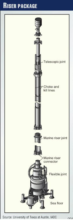
The riser package, consisting of the following components, mounts rigidly to the seafloor (Fig. 7):
- Lower flex joint mounted on top of the lower marine riser package (top of BOP)
- Marine riser connector
- Marine riser string
- Choke and kill lines
- Telescopic joint
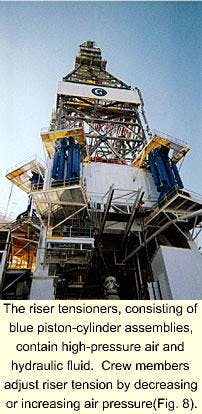
- Marine riser tensioners (Fig. 8).
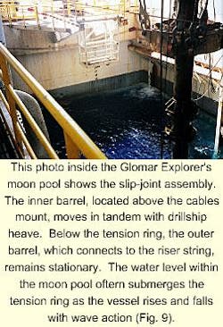
The telescopic joint, often called the slip joint, compensates for heave between the drillship and marine riser (Fig. 9). Essentially, it is a special tube, or barrel, that slips inside the riser pipe.6
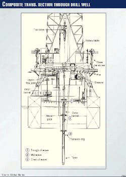
The inner barrel, connected to the rig, moves up and down with it (Fig. 10). Because the outer barrel is part of the riser pipe, it remains stationary with respect to the seafloor.
A tension ring, mounted around the outer barrel of the telescopic joint, attaches to steel cables with large padeyes (Figs. 9 and 10). These cables reeve through sheaves mounted on the underside of the drill floor. Each cable goes through a sheave and connects to a marine riser tensioner (Fig. 8). Whereas the Glomar Explorer uses 8 tensioners, the C.R. Luigs will use 12.
"Upward pull must be applied to the riser, or else it will buckle under its own weight," said Charles Keaton, vice-president of engineering/operations support for Global Marine. Additionally, drillers must compensate for vortex-induced vibrations (VIV).
"We're worried about the fatigue life of the risers," Dreith said. "What happens is as ocean currents push water past the riser, it creates an eddy on the back side. This can start a vibration." In essence, this generates high pressure on one side and low pressure on the other, producing harmonic resonance.
Currently, engineers use two methods to deal with VIV, especially problematic in the GOM where there are eddy and loop currents. One method includes installing spoilers on the riser pipe OD, similar to those mounted on smokestacks. These serve to break up the destructive vibrations.
"We used this method of VIV abatement on the Glomar Explorer on its first well," Keaton said. Or instead, "We end up compensating for VIV through brute force; that's why we have the 3.5 million lb tensioning ability."
However, "There's a lot of different schemes out there to monitor the problem, including the placement of sensors along the riser that send real-time acoustic signals back to the surface. But nobody has yet developed a (working) vortex system on a drilling riser other than the spoiler."
In many cases, more than 3 million lb of tension must be applied to offset the effects of buckling and VIV.
Neutralizing drillstring motion
In any floating drilling operation, the rig must compensate for heave on the drillstring; otherwise the drill bit will bounce on the bottom of the hole, making drilling nearly impossible.
Heave pulls weight off the bit as the floating rig rides to the crest of a wave and places weight back on as the rig rests in the trough.6 Thus, drillships must compensate for vertical drillstring movements induced by a heaving vessel.
Heave compensators consist of a piston-and-cylinder assembly that are either crown mounted at the top of the derrick or mounted directly under the traveling block. Both types of motion-compensation systems work to maintain relative position between the top drive and the bottom of the well.
The piston strokes up and down within the cylinder as the ship moves, keeping the hook and top drive in a fixed position relative to the seafloor.6
The Glomar Explorer uses an active-drive, crown-mounted compensator manufactured by Shaffer (Varco Co.). An active drive reacts differently than a passive drive in that the system attempts to anticipate up-and-down movements instead of reacting passively.
The system measures real-time rig displacement by integrating signals derived from an accelerometer and two inclinometers. From this continuous calculation, the system adds or subtracts the residual motion imparted to the drill string by applying a pulling or pushing force to the crown block.
The work done by the system removes up to 95% of the unwanted excitation imparted to the drill string by the passive compensation system.
The active compensating system on the Glomar Explorer includes a central control unit (CCU), operator's panel, position sensor, actuating cylinder, hydraulic power unit (HPU), and control container. The CCU continuously monitors the rig heave, compensator position, accumulator position, and system pressure.
It generates a compensating demand system using a sophisticated control algorithm to drive the HPU. The operator's panel contains eight control buttons that are wired directly to the CCU.
The position sensor, connected to the outer barrel of the marine riser's telescoping joint, records the linear motion of the compensator, riser tensioners, and rig heave by measuring movement along the guideline tensioners.
The unit, containing a spring motor and wire drum, connects to an angular sensor using a timing belt and gear wheels. An additional heave sensor, mounted vertically near the center of the rig, also uses a high-resolution accelerometer.
References
- Munden, A., "Classification of control and power systems for dynamic positioning," presented at the Marine Technology Society's Dynamic Positioning Conference, Oct. 21-22, 1997.
- Rokeberg, H., "Presentation of DP Class 2 and Class 3," presented at the Marine Technology Society's Dynamic Positioning Conference, Oct. 21-22, 1997.
- Dreith, M.W., Garvin, M.D., and Thorson, J.A., "Glomar Hull 456 Class Ultra-Deepwater Drillship," SPE/IADC paper 52858 presented at the Annual Drilling Conference, Amsterdam.
- Burleson, C.W., The Jennifer Project, Texas A&M University Press, 1997.
- Dietmar, D., "Principal aspects of thruster selection," presented at the Marine Technology Society's Dynamic Positioning Conference, Oct. 21-22, 1997.
- Baker, R., A Primer of Offshore Operations, 3rd Edition, University of Texas at Austin in cooperation with the International Assoc. of Drilling Contractors, Houston, 1998.
