Method sizes multiphase-flow gathering lines
A methodology developed for sizing multiphase-production gathering lines was applied by Texaco Inc. in the Aneth oil field to determine flow line sizes for its CO2 flood operation.
The Aneth example shows the potential advantages that multiphase-flow gathering lines offer to field operations and project cost savings. But if the lines are not appropriately sized, a multiphase-flow system can be a detriment for operations.
Large-scale dual liquid and gas gathering systems have historically been avoided because of uncertainties and problems inherent in the character of multiphase-flow lines. However, if designed properly, a multiphase-flow system may improve field operations and field economics.
In addition and, contrary to popular belief, in the proper circumstance multiphase-flow systems may lower gathering line and wellhead pressure.
Recent advances in surface-facility simulation allow engineers to better predict the character and consequences of collecting all fluids in a single gathering line. The possible advantages shown by these simulations indicate that the option of multiphase flow should be considered when designing new liquid and gas gathering systems.
Potential applications
The potential economic benefit and operational improvement that is provided by multiphase-flow lines is applicable to a wide variety of projects. For example, in offshore oil and gas development, a subsurface production system can include a multiphase-flow gathering line to deliver all produced fluids to a land-based separation facility.
This removes the potentially prohibitive cost associated with the construction and maintenance of a fixed platform with separation facilities.
Another application might be in offshore arctic conditions, where this method could eliminate capital costs associated with building large ice-resistant platforms. In onshore development, multiphase production gathering enables the operator to reduce satellite facilities and line mileage.
Whether onshore or offshore, large or marginal, old or new, multiphase-flow gathering lines have the potential to improve field operation and economics.
Aneth Unit
The Aneth oil field is a compelling example because it demonstrates how multiphase production gathering was designed and applied to a mature, onshore field with complex terrain and dynamic fluid levels. Additionally, the Aneth example shows how multiphase production gathering can improve tertiary recovery economics.
This is becoming an issue of growing importance as North American fields deplete.
Texaco`s Aneth Unit is in a topographically complex region of southeastern Utah. The field has been operated as a waterflood since 1955.
The unit encompasses about 24 sq miles and has 14 sites where oil, water, and gas production facilities are located. Approximately 200 miles of production gathering lines and 90 miles of water injection lines are used in daily operations.
In 1998, the surface facilities were redesigned as part of a plan to begin a carbon dioxide (CO2) miscible flood. At that time, the field produced about 4,500 bo/d, 60,000 bw/d, and 3.5 MMcfd.
Many U.S CO2 floods have substantially increased hydrocarbon recovery; however, CO2 floods risk economic failure due to large, necessary, up-front investment. A slim operating margin during a time of low oil prices means that facility-related expenditures could "make or break" CO2 project economics.
When implementing a CO2 flood, there are numerous facility engineering challenges and decisions that must be made. The assessment of multiphase-flow gathering lines is one such decision that could be made.
Facility design
Before the CO2 project began, hydrocarbon production was collected at satellite facilities. Two satellites are discussed in this article. Although these two satellites are less than 1 mile apart, their elevation differs by over 200 ft.
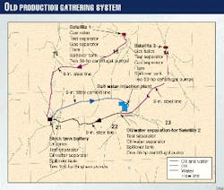
The stress placed on production gathering lines and pumps by elevation changes has resulted in two distinctly different paths to the same battery (Fig. 1).
Each satellite consists of a well test manifold, test separator, gas separator, flare, spillover tank, and two centrifugal pumps. At each satellite, the gas is separated, metered, and sent to a nearby sales line.
The centrifugal pumps send the combined oil and water through a single line to a stock-tank battery where the oil is separated from the water and sold. At the battery, additional centrifugal pumps are required to send the water through a transfer line to the water-injection plant. CO2 is injected into the reservoir at high pressure, as a liquid.
As CO2 travels through the reservoir and approaches the production well bore pressure, a large portion of the CO2 is in the gas phase. This CO2 contaminates the associated produced hydrocarbon gas, which can no longer be sold. Instead, the contaminated gas is sent to a compressor station where the CO2 and hydrocarbon gas are repressurized to a liquid phase for reinjection.
Thus, CO2 is repeatedly recycled, reducing the need to purchase new CO2.
Because the CO2-contaminated gas volume was expected to be more than 10 times current gas production, a new system was needed that was capable of delivering this gas from the satellites to the recycle compressor, more than 2 miles away. For the design, Aneth engineers re-evaluated:
- Efficiency of the current system
- Effect of elevation on production gathering facilities
- Merits of centralizing fluid collection and handling facilities.
The initial and full-life cost, operational improvement, and the expected life of existing liquid gathering lines and facilities were all factors in evaluating the two facility options of either a traditional or a multiphase-flow system.
Traditional system
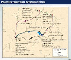
The first option was to continue separating gas at each satellite in a traditional fashion. The produced gas and liquid would be sent in separate lines to two different locations.
To minimize line mileage, a single gas line would be built to connect the two satellites to the CO2 recycle compressor. The produced oil and water from each satellite would continue through the existing gathering lines, en route to different batteries (Fig. 2).
CO2 has a strong tendency to stay in solution. Therefore, when the liquids reach stock-tank conditions, large volumes of CO2 gas are released. Consequently, the existing vapor-recovery systems would have to be enlarged at each battery. Worse yet, the collected vapor from the stock tanks would be CO2 contaminated, and an additional line to the recycle compressor would need to be built.
Multiphase-flow system
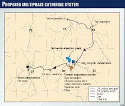
The alternative was to remove all but the test separator at both satellites and send oil, water, and gas in a single line from one satellite to the other. At this point, all fluid from both satellites would be commingled and sent to a central location near the compressor station and water injection plant.
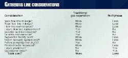
All necessary separation facilities and the vapor recovery system would be located at this central location. Fig. 3 illustrates this multiphase-flow gathering design. Table 1 summarizes this system`s advantages.
With a multiphase-flow system, the need for separation facilities and related pressure drop at the satellites was removed. Therefore, the centrifugal pumps were no longer needed to repressurize the liquid for transport.
After eliminating the separators and centrifugal pumps, each well`s downhole pump would be sufficient for moving the fluid to the central separation facility. In doing so, the hydrostatic head-caused elevation changes became less of an issue. Therefore, a line that combined the production from both satellites could be built, reducing overall gathering line mileage and installation cost.
This option`s additional benefit was better corrosion resistance. If the traditional system was selected, oil and water would continue to travel through the old, steel production line. The carbonic acid in the line, because of elevated CO2 concentrations would cause accelerated corrosion, requiring chemical corrosion inhibitors and extra line maintenance. Line replacement, in time, was also probable.
Future problems associated with line corrosion were removed by combining all fluids in a single, corrosion-resistant, fiber glass line.
By eliminating satellite separation facilities, the engineers could remove the flares and emergency spillover tanks from the system.
The old test separator was replaced with an improved, automated system capable of obtaining faster, more-accurate well test measurements. The elimination of satellite equipment clearly reduced the need for satellite maintenance, and regular visits by field personnel were no longer necessary.
Only one vapor-recovery system was needed because of the centralized gas and liquid separation at one location, next to the recycle compressor. The length of the vapor recovery gathering line was reduced to a few feet, rather than miles.
Furthermore, because the water-injection plant was nearby, the need to continuously pump produced water through a transfer line from each battery was eliminated. The central separation facility also reduced the number of vessels and installation cost.
Environmental sensitivity improved because of the retirement of old gathering lines, along with the overall reduction of total line mileage, spillover tanks, flares, vessels, and surface-facility acreage. As additional satellites are added to the CO2 flood, the multiphase-flow option and the central separation facility will provide the same economic and operational benefit experienced by the first two satellites.
Consequently, the field and project economics will benefit from minimized capital expenditure and reduced operating cost.
Horizontal multiphase flow
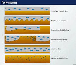
When liquid and gas are transported together in a single line, the fluids travel in different configurations known as flow regimes. The dominant flow regime will vary according to flow rate, line diameter, line inclination, and fluid properties. Many complex phenomena are associated with each flow regime (Fig. 4).
Stratified flow
Liquid and gas in a single line will separate due to different densities. At low flow rates, the fluids will stratify with the gas on top. This is called stratified flow and is one of the most dominant flow regimes in horizontal and near-horizontal lines.
As the combined fluids move downstream, the gas travels faster than the liquid and "slips" by it. This phenomenon is called slippage. Slippage retards the liquid`s ability to flow. As a result, the liquid tends to "bulk-up" in the line. This is called "liquid hold-up."
The amount of liquid hold-up is proportional to the degree of slippage. Line pressure increases as the liquid "bulks-up" in one area of the pipe.
During stratified flow, waves may develop due to interfacial shear, once the system exceeds a certain velocity. In a positive feedback process, the "wavy" turbulence increases the interfacial shear between the two fluids.
This phenomenon reduces slippage and increases frictional "drag" at the gas-liquid interface. This may result in the gas assisting the liquid flow. In the right circumstance, the pressure in a multiphase-flow line may be less than a line with liquid only.
Intermittent flow
When multiphase waves become unstable or large, the fluids may pass into the intermittent flow regime. Intermittent flow is characterized by alternating volumes of liquid and gas. This phenomenon is known as "slugging" and also occurs because of liquid pooling in low areas of the line, unsteady fluid rates, and excessive increases in fluid velocity.
Slugging is the source of many troublesome engineering problems. Extreme slugging can violently rock separation facilities and overwhelm their capacity with sudden and large volumes of gas or liquid.
Intermittent flow causes large increases in line pressure and sudden pressure pulses that can threaten line integrity. In all circumstances, slugging is to be avoided.
Bubble, annulus flow
The dispersed bubble-flow regime may develop on a highly liquid-dominated multiphase system, whereas, the annular flow regime may develop in a highly gas-dominated system.
These two flow regimes are the source of few engineering concerns. Unfortunately, compared to stratified and intermittent flow, these flow regimes are infrequent and rarely attained.
Therefore, when designing a multiphase system, engineers should place greater emphasis on understanding and controlling the stratified-intermittent transition.
Smaller lines
For a given application, gathering line diameter will control which flow regime is dominant. If possible, it is preferable to size the gathering line so that wavy stratified flow is encouraged. In this manner, slippage is reduced and the liquid may experience "lift" from its gas counterpart.
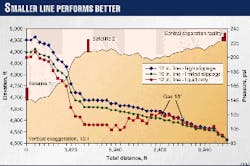
Fig. 5 displays the simulated line pressure response expected at Aneth due to the elevation and a desired outlet pressure of 90 psi at the compressor. This figure demonstrates that when designing a multiphase-flow line, bigger is not always better.
With a smaller line diameter, the system`s velocity adjusts so that slippage is minimized, and wavy stratified flow is dominant.
In fact, for the last 5,000 ft, the smaller multiphase-flow line displays a lower pressure response than a line with liquid only. If the line is sized too small, however, wave stability may deteriorate and the system velocity will encourage intermittent flow.
Intermittent flow may also develop if the pipe is sized too large. Therefore, it is crucial to carefully consider the expected throughput and determine the effect of line diameter on pressure and slug control.
Sizing multiphase lines
In the petroleum industry, uncertainty is the norm. On a daily basis, petroleum engineers make predictions, designs, improvements, and decisions based upon rough estimates and imperfect data. The design of multiphase-flow lines is not an exception.
For proper sizing of multiphase-flow lines, engineers need to know the volume of gas and liquid to be collected. But fluid rates are usually variable and can be erratic because of downtime, accelerated decline, unexpected production, or infill drilling.
In the Aneth Unit, the expected fluid volumes were highly dynamic because of the first fully horizontal CO2 injection and production pattern. Aneth reservoir engineers forecast that, within a few years, gas production from the area of interest might increase to 11 MMscfd from the current 0.8 MMscfd. Additionally, the water-alternating-gas injection program and incremental recovery were the source of more volume variability. The Aneth facility engineers had to appropriately size a multiphase-flow line that would perform best under all these dynamic conditions.
Any credible recommendation to use a multiphase-flow system must be rigorous enough to out-perform other designs across the expected range of flow rates.
After numerous simulation runs, the engineers established a relationship between expected line pressure and liquid volume as a function of throughput for numerous pipe combinations. Flow-pattern maps were observed at each condition and at several locations along the line so that intermittent flow could be avoided as much as possible.
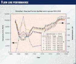
The facility simulation results were combined with the reservoir engineering forecast to create the graph displayed in Fig. 6. This graph demonstrates that the larger pipe performs well during peak conditions, but performs the worst for 20 of the 25 years in the project.
This graph, therefore, was used to select a line size that performs adequately during peak production, but optimally over the life of the project. As a result, the line selected was smaller, better performing, and less expensive.
When throughput cannot be exactly predicted, probability can be associated with each volume estimate. In this way, even uncertainty can be factored into this methodology, resulting in the selection of a line that best serves the application. Fig. 6 enables reservoir and facility engineers to work together to determine the consequences of multiphase flow on reservoir performance, field operation, and project economics.
Aneth engineers used this methodology to choose the 10 and 14-in. line combination, rather than the two larger combinations that only perform well at flow rates greater than 7 MMscfd.
The economic and operational benefit of multiphase-flow lines can be widespread. However, it must be understood that there are still some uncertainties in the nature of multiphase flow in pipe. The number of multiphase models and correlations are numerous and different circumstances require the use of different models.
Advancement in simulation accuracy and user-friendly software is steadily reducing the difficulty inherent in multiphase-flow line design. The engineers, however, need to understand all simplifying assumptions and limitations built into the simulation. It is essential that all available data, including flash and fluid properties be carefully incorporated into the multiphase model.
Multiphase flow is a new and emerging technology with considerable potential, but it is not a cure-all solution. To be beneficial, multiphase flow requires careful and thorough analysis in its design and implementation.
Aknowledgments
The authors would like to thank Texaco Exploration & Production for allowing the publication of this article. We also would like to recognize the cooperation and efforts of Steve Froning, CO2 reservoir engineer for the Aneth Unit and acknowledge Richard Christiansen of the Colorado School of Mines for reviewing the description of flow regimes.
Bibliography
- Brill, J.P., and Arirachakaran, S.J., "State of the Art in Multiphase Flow," JPT, May 1992, pp. 538-41.
- Brill, J.P., "Multiphase Flow in Wells," JPT, January 1987, pp. 15-21.
- El-Oun, Z., "Gas-liquid Two-phase Flow in Pipelines," SPE Paper No. 20645, 65th Annual Technical Conference, New Orleans, 1990.
- Hill, T.J., and Wood, D.G., "Slug Flow: Occurrence, Consequences, and Prediction," SPE Paper No. 27960, University of Tulsa Petroleum Engineering Symposium, Tulsa, 1994.
- Marcano, R., Chen, X.T., Sarica, C., and Brill, J.P., "A Study of Slug Chraracteristics for Two-Phase Horizontal Flow," SPE Paper No. 39856, International Petroleum Conference, Villahermosa, Mexico, 1998.
- Oliemans, R.V.A., "Multiphase Science and Technology for Oil/Gas Production and Transport," SPE Paper No. 27958, University of Tulsa Petroleum Engineering Symposium, Tulsa, 1994.
- Xiao, J.J., Shoham, O., and Brill, J.P., "A Comprehensive Mechanistic Model for Two-Phase Flow in Pipelines," SPE Paper No. 20631, 65th Annual Technical Conference, New Orleans, 1990.

