High-torque gear reducer expands turbodrill capabilities
New developments in turbodrill technologies, aided by high-torque gear reducers, hold promise for horizontal and vertical drilling applications.
For several decades, the Russian turbodrill has traditionally been used for drilling oil and gas wells in the Former Soviet Union. Throughout the early 1990s, this technology drilled more than 32 million m annually with current footage encompassing about 75% of the total drilling volume.
Over the last few years, however, new bit designs fitted with oil-filled bearings, along with the development of horizontal drilling technologies, have resulted in reduced turbodrill drilling volumes as compared to other systems. These reduced drilling volumes were caused by the shortcomings of:
- The great length of the turbodrill assembly
- Extremely high rotational speeds
- Low torque.
World over, high-torque, low-speed, positive-displacement motors (PDMs) have become more commonly used, finding successful applications for drilling deviated and horizontal wells. Under conditions of elevated bottom-hole temperatures (BHTs), however, along with the use of diamond and high-speed polycrystalline diamond compact (PDC) bits, the need for heat-resistant downhole motors has become a necessary requirement.
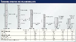
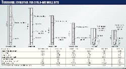
This has led to the development of the gear-reduction turbodrill, from which over the past 35 years, a large amount of work has been carried out. The result of this work, regarding improvements in the power characteristics, can be traced to the development of turbodrills used for drilling with 215.9-mm bits (Fig. 1).
Improvements in the technology enabled a:
- Reduction in turbodrill length from 25.7 to 5.9 m
- Reduction in speed of bit "no-load" rotation from 768 to 194 rpm
- Four-fold increase in stall torque
- Reduction in turbodrill OD from 195 to 178 mm.
These improvements helped alleviate many downhole drilling problems such as differential sticking while improving overall well quality. Furthermore, heat-resistance of the gear-reduction turbodrill was elevated to 250° C. Analogous results were obtained in the course of development of the other standard-size gear-reduction turbodrills.
History
In 1923, Mikhail Kapelyushnikov pioneered development of the gear-reduction turbodrill. In the beginning, he developed a one-stage turbine, in conjunction with a planetary tooth gear, mounted within an oil-filled chamber.
Later, multistage turbines with two and three-stage planetary gear reducers were used to maximize power. From 1935 to 1938, Pyotr Shumilov proceeded with the development of multistage turbodrills using multistage planetary gear reducers. Unfortunately, the low resistance of the planetary gears and seals did not allow for long motor life.
In the early 1950s, Georgi Lyubimov attempted to develop a turbodrill with the multistage turbine and gear reducer capable of operating in drilling mud. Afterward, in the 1960s, several organizations became involved with the development work including the Russian Research Institute of Drilling Technologies (Vniibt), the Institute of Oil & Gas, and the Kungur Machine Building Plant.
At the same time, gear reducers were also developed for the electrodrill in Russia and the U.S. The use of gear-reduction turbodrills in the U.K. was also carried out. The quality of the sealing devices and the life of gear reducers during that period of time, however, did not meet the necessary requirements for industrial application.
During the early 1970s, in Kharkov, Ukraine, oil-filled gear-reduction inserts for the electrodrill were developed. Then in 1975, successful commercial development of the gear-reduction turbodrill was achieved by the Perm branch of Vniibt.
Finally, in the early 1980s, Canadian engineer Ken Wenzel also began to develop oil-filled, gear-reduction PDMs for such companies as Maxi-Torque Drill Systems Inc., Computalog, and Vector Oil Tool Co.
Research and development
Research into downhole motor dynamics and oil-protection system technologies preceded gear-reduction design. During this time, problems concerning the impact of twisting and longitudinal and lateral vibrations of the gear-reduction turbodrill, were solved. It was found that the deeper the well, the more difficult it became to overcome these tendencies.
To provide high reliability for the gear reducer and oil protection system, it became necessary to evaluate the dynamic processes and take into the account the dynamic loads when calculating component strength.
Mathematical models such as the three-weight model and model of weights were used to help design the turbine section and gear reducer.1
From this research, it was possible to equip the planetary gear reducers with devices that compensated for excessive deformations that usually occur under dynamic loads.
The mathematical model for the oil-protection system took into account two downhole dynamic factors consisting of mud-pressure pulsation and axial vibration. As a result, the optimum magnitude of hydraulic discharge for the top and bottom face seals were defined while the lubricator parameters and cross sections of the oil ports were optimized.
The above studies of dynamics and hydrodynamics were of use for development of the TRM-195 gear-reduction turbodrill. The results were verified in dynamic tests that used a drilling test stand and granite block lined with steel and lead bottoms.
The results were also recorded during drilling of an experimental well situated on the testing ground of the Perm branch of Vniibt at a depth of 1,700 m.
The wire line telemetry system, STT-164, commonly used in electrodrill applications, was used to measure rotational speed, torque, and axial load.2 In addition, the mathematical model of the oil-protection system was checked in experiments with strain gauges by measuring the pressure pulsation of the mud and the oil pressure in the top and bottom seal of the TRM-195 while drilling the granite block and steel bottom.
Final field testing of the TRM-195 occurred in Tatarstan, Bashkiriya, and West Siberia. From 1975 to 1981, pilot production of the TRM-195 began in the Perm branch of Vniibt and the Kungur Machine Building Plant. Then in 1982, the Polimermash Plant located in Tambov, Russia, started serial production of the oil-filled gear reducers TRM-195 and the turbodrill TRM-195 spindles.
Gear-reducer design
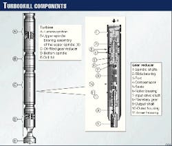
The design of the first batch-produced turbodrill TRM-195 consists of (Fig. 2):
- One or two turbine sections (A)
- A bearing assembly of the upper spindle (B) located on the shaft from which the turbine shaft rests
- An oil-filled gear reducer (C)
- A bottom spindle (D) located on the output shaft which the drill bit (E) is screwed into.
The upper (B) and lower (D) spindles discharge the gear reducer (C) from the axial loads. The gear reducer (Fig. 2), located in the lower central portion of the turbodrill, is a self-sufficient unit that is interconnected at the shaft ends with spindle shafts by virtue of half-clutches (1).
The housing (10) is joined to the spindle housings by means of sub-tapered threads. The gear reducer contains an input drive shaft (7), planetary gear (8), and an output shaft (9). Each of the shafts is installed on a radial spherical roller bearing (6) and a radial slide bearing (2) between which a seal (5) is mounted to separate the oil-filled chamber from the mud compartment.
Two seals (5) with an inner housing (11) and compensator (4) form an oil-filled, chamber-protection system in which the planetary gear (8) and rolling bearings (6) are mounted. The drilling fluid passes through an annular channel between outer (10) and inner housing (11).
Oil is injected into the chamber through the port (3) located in the outer housing (10). The compensator (4) transmits the drilling fluid pressure and compensates for oil leakage through seals (5). The gear ratio for the planetary gear is 3.69.
It is also possible to use two such gears sequentially. In this case, the gear reducer gear ratio is equal to 13.62.
The turbodrill is provided with a specially developed double-row planetary gear using Novikov`s helical gear design. This design features an automatic distribution of load, improvements in torque transmittal, enhanced bearing members for the shafts, and an oil protection system with seals and a compensator.
The 195-mm OD gear-reduction turbodrill of the TRM class is widely used in the fields of West Siberia, the Urals, and the Volga region. The total drilling volume has exceeded 3.5 million m with an annual penetration volume of 400,000-600,000 m. The mean time between failure (MTBF) for the oil-filled gear reducer works is more than 200 hr.
Western drill bits
Over the past few years, Russian oil companies have begun to use drill bits from Western companies like Hughes Christensen, Smith International, and Reed Tool Co. in conjunction with PDM motors and gear-reduction turbodrills. In Western Siberia, these assemblies are commonly used in the lower, hard-to-drill intervals with depths ranging from 2,000 to 3,000 m. Empirical data reveal that the best results are achieved when these bits are used with the TRM-195 gear-reduction turbodrill.
The run analyses for 127 Hughes Christensen`s ATM-11N, 215.9 mm drill bits, using the TRM-195 with a flow rate of 30-32 l./sec and rotational speed of 180-200 rpm, achieved an average of 969 m per bit. There was a penetration rate of 8.4 m/hr, and bit life was 116 hr.
Compared to traditional drilling technology, the footage per bit increased 7 to 10 fold, and penetration rates increased 8-10%. The power characteristic parameters, life, and reliability of the TRM195 increased the effectiveness of the above drill bits.
Heat resistance
One of the most important advantages of the gear-reduction turbodrill, as compared to the PDM, is its ability to operate at 150-250? C. As stated, the temperature range for PDMs is limited by the heat resistance of the elastomer and the temperature limitation of the adhesive used for bonding the rubber lining with the metal stator housing.
For the following reasons, the conventional gear-reduction turbodrill incorporates members that lose their serviceability in temperatures exceeding 150-180° C:
- The rubber-metal radial bearings and sleeves are produced out of low-carbon steel with the surface case hardened by carbon.
- The rubber sealing O-rings do not efficiently carry mechanical loads.
- The lubricants are made of poor quality.
The idea of a heat-resistant downhole motor, featuring comparatively low rotating speeds (lower than the nongear-reduced turbodrill), arose in 1975 for drilling the Kola ultra-deep well at depths beyond 8,000 m and a BHT of 150° C. and greater. Further applications occurred for drilling additional ultra-deep, scientific, and geothermal wells.
Increasing the heat-resistance for the gear-reduction turbodrill was provided by replacing the bearings, O-rings, and other components with more-expensive, yet highly heat-resistant materials. The radial slide bearings, made of rubber-metal members, were changed out with bearings made of hard alloy, increasing the wear resistance even under normal temperatures. This became especially significant for high-speed turbine shafts.
Because the original steel was tempered at relatively low temperatures (150-250° C.), it was found that the metal lost its durability at high downhole temperatures. For this reason, the metal was replaced with high heat resistant or hard-alloy material.
O-rings, serving as secondary seals for stationary connection clearances, or connections characterized by low reciprocating travel, do not bear high mechanical loads. Thus, they are wear resistant.
Currently, some elastomer materials that operate in the range of 250-300° C. (maximum) have been developed. For example, aviation rubbers based on fluoroelastomer have found wide application in addition to other materials such as silicone rubbers.
The testing of rubbers in super-heated water reveal that silicone rubber swells in this medium. One type of fluoroelastomer, however, provided excellent results when heated to 250° C. in oil for 50 hr. In water temperatures of 150° C., however, it lost its elasticity, and was covered with cracks after 15 hr.
The most serviceable components under these conditions proved to be a fluoroelastomer rubber invented by the St. Petersburg Institute of Synthetic Rubber. Oil-resistant rubber produced by several, such as Viton and Calrez, also provided temperature resistance up to 200° C.
In the course of lubricant selection, it was revealed that the mineral Cylinder-52 oil (a Russian product) became the most suitable product for these conditions with heat resistance up to 300° C. and a viscosity of 50 centistokes at 100° C. The high viscosity and strength of the lubricant film, in addition to its low price, allowed its use not only for heat-resistant gear reduction applications, but also for turbodrill gear reducers used under normal temperatures.
Gear-reduction turbodrills suitable for high temperature conditions have been tested in a high-pressure, high-temperature testing unit (HPHT) followed by a field run (OGJ, Dec. 7, 1998, p. 71). The heat-resistant version of the TRM-195 turbodrill enabled scientists to drill a number of ultra-deep wells within the network of National Program of Earth`s Mantle Drilling in addition to the world`s deepest well (Kola) from 8,150 to 12,260 m deep (1979-1992).
For this purpose, it became necessary to increase the heat resistance for a number of turbodrill components and gear-reduction parts up to 250° C.
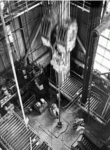
Fig. 3 shows the heat-resistant (to 250? C) gear-reduction turbodrill TRM-195 being run to the depth of 12,237 m in the Kola well. The heat-resistant option of the gear-reduction turbodrills has also been successfully used for drilling lower intervals of the Saatlinskaya, Timano-Pechorskaya, Dneprovo-Donetskaya, Krivorozhskaya, and Tyumenskaya super-deep wells. Currently, the Uralskaya super deep well is being drilled by the gear-reduction turbodrill with more than 9,000 m of hole drilled by gear-reduction turbodrills in super-deep wells. This experience has revealed distinct heat-resistance advantages over PDM motors and nongear-reduced turbodrills. For example, from 11,200 m to 12,260 m in the Kola superdeep well, the MTBF for the gear reduction-insert RM-195 exceeded 460 hr.
Increasing use
The successful application of the TRM-class, gear-reduction turbodrill proved the possibility for providing a reliable sealing system that can be upgraded to meet the requirements for modern drilling equipment and technological advances.
These requirements were put forward because of the increasing use of horizontal and directional drilling applications, and the wide application of high-capacity PDC bits.
The requirements consist of a:
- Reduction of downhole motor length required for accurate well path control
- Reduced distance between the bit and bent-angle sub
- Need for increased rotational bit speed (400-500 rpm) while preserving high magnitudes of drive torque
- Availability of increased life and dependability of the turbodrill, especially under elevated temperatures exceeding 150-200° C.
The reduction of the gear-reduction turbodrill`s length was accomplished by introducing new thrust rolling bearings (slide bearings) installed in the gear reducer`s oil-filled chamber. The new gear-reduction spindle is thus 2.5 to 3 times shorter than the TRM195 spindle.
Furthermore, the possibility of varying the gear reducer`s gear ratio allowed for the creation of high-speed, high-torque turbines of enhanced efficiency. The elevated levels of torque were achieved with fewer turbine stages, resulting in the reduction of the turbodrill`s length.
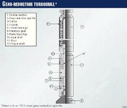
Fig. 4 shows the diagram of the gear-reduction turbodrill fitted with a gear-reduction spindle of the RSH class. The turbodrill contains a turbine section (1) with conventional high-speed turbines located on the shaft (11) and a gear-reduction spindle (2) located on the shaft which the drill bit (3) is screwed into.
The gear-reduction spindle consists of input (10) and output (12) shafts and a planetary gear (8) mounted in an oil-filled chamber between seals (4 and 5). This chamber incorporates axial bearings (6 and 7) and radial bearings (9) for the shafts. The total length of the gear-reduction spindle does not exceed 3-4 m.
If necessary, a bent sub can be mounted between the turbine section and gear-reduction spindle. The total length of the turbodrill is 1.5 to 3 times less than the TRM turbodrill class. The batch production of the turbodrills with gear-reduction spindle is now under way by Neftegastechnika in Perm.
A further decrease in the gear-reduction turbodrill`s length and the placement of the bent sub closer to the bit requires installation of the flexible shaft between the planetary gear and the output turbodrill shaft located in the oil-filled chamber.
This design has been jointly developed with the German company Tiebo Tiefbohrservices GmbH & Co. These turbodrills, with a distance of 1.5-2 m from the bit to the bent-angle sub, are shorter than the turbodrills that incorporate a gear-reduction spindle.
The development of high-speed turbines enables rotating speeds of 300-500 rpm under normal operating conditions and twice as large at no-load conditions.
As a rule, the rotational speed of the turbodrill`s output shaft, while drilling, constitutes the average of rotating speeds while operating and under conditions of no-load, dependent on bit weight. This condition, in combination with a high-torque capability, provides optimal operating parameters for drilling with PDC bits. (Fig. 5 at right)
The configuration is preferable over low-speed, high-torque drilling conditions provided by PDMs and the high speed but considerably low torque of nongear-reduced turbodrills. (Fig. 6 at right)
The efficiency of these high-speed turbodrills has been proven in Egypt, Germany, and Saudi Arabia (1997-1998). The performance of several gear-reduction turbodrills is presented in Table 1.
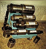
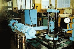
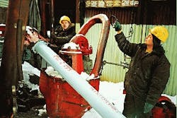
The planetary tooth gears for 120 mm to 240-mm OD gear-reduction turbodrills are shown in Fig. 5. Fig. 6 (both above) shows the test stand used during the testing of the planetary gear. Fig. 7 (at right) presents assembly procedure of the gear-reduction spindle RSH2-195.
Acknowledgment
The authors wish to thank the engineers and scientists at the Perm branch of Vniibt, Neftegastechnika, Perm State University, the Geological Survey Co., the Kungur Machine Building Plant, Tambovpolimermash Plant, and a number of oil production companies of West Siberia and the Urals.
The authors also wish to thank Tiebo Tiefbohrservice GmbH & Co. for their participation in the development, testing, operating, servicing, and improvement of these turbodrills.
References
- Girshik, B.L., and Landik, L.V., Mathematical Modeling of Longitudinal and Torsional Vibrations of Hydraulic Downhole Motors, Publishing House of Perm University, 1992, p.160.
- Chepelev, V.G., et al., "Methods of Deflector Orientation at the Bottom Using Telemetry System," Oil Industry Journal, Moscow, 1971, No. 11.
The Authors
Nikolai D. Derkach is general director of the Research Development Co.-Neftegastechnika, in Perm, Russia. He was previously with the Kungur Machine Building plant (1961-1964) as a turbodrill designer and with the Perm branch of Vniibt (1964-1992) as the chief and later director of the gear-reduction turbodrill department. Derkach holds 52 patents and is a doctor of technical sciences.
Ernst N. Krutik is deputy director of science for the Research Institute of Drilling Technologies-Vniibt, in Perm, Russia. He was previously the chief of the gear-reduction turbodrill department for this institute. Krutik holds 37 patents and is a doctor of technical sciences.
