Teamwork, downhole technology expedites Tierra del Fuego operations
EXTENDED-REACH DRILLING-Conclusion
Roland Vighetto, Matthieu Naegel, Emmanuel Pradi?
Total Austral SA
Tierra del Fuego, Argentina
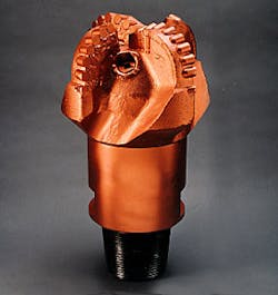
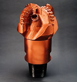
A bit similar to this four-bladed, 12¼-in., Diamond Products International polycrystalline diamond compact, drilled a single-footage world record of 22,221 ft in Total's Cullen Sur No. 1 well, located southeast of the Cullen Norte No. 1. Average penetration rates achieved 100 ft/hr over a period of 221 hr. The previous single-footage record of 15,579 ft was set in 1994 (Fig. 2).Building on the success of 10 extended-reach wells in Tierra del Fuego, Argentina, a multidisciplinary team recently drilled a world-record, horizontal-displacement of 10,585 m (34,728 ft), using a combination of innovative and time-proven technologies ( Fig. 1 [62,888 bytes]).
This conclusion of a two-part series, which began May 17, p. 51, describes how Total Austral SA, Deminex, and Pan American Energy, in close coordination with the contractor and service providers, overcame logistical, technical, and geological barriers to drill a complex well configuration to a TD of 11,184 m measured depth (MD).
Team management
Without a complete understanding of hole cleaning processes, rig equipment selection and operation, and drill pipe and tubular design, 1 it would have been next to impossible to drill the Cullen Norte No. 1. Thus, proper engineering practices, managed by a localized group of key stakeholders, became the dominant success factor for this well.To assist in these efforts, the project team's base office was moved to Rio Grande, Tierra del Fuego, in 1997, serving to expedite communications between rig and office staff.
Located only 2-3 hr from the well location, supervisory personnel were able to foster close working relationships with rig personnel, promoting the two-way flow of ideas. The main benefits of this exchange included a heightened grasp of the physical processes by the office staff while allowing well-site personnel to take part in all aspects of the decision making process.2
Procurement
A secondary benefit for a localized base office included vast improvement in the logistical control of procurement procedures between the remote well sites and the major service, consumable, and hardware centers located in the U.S. and Europe. This became especially important because disruptions in equipment or supply delivery, with very little advance notice, could shut the drilling operations down for a lengthy period of time.For example, importing mud products from Houston, located 12,000 km (7,500 miles) away, requires two ships, three custom clearances, and additional trucking-all of which can take 2-3 months depending on the weather. These conditions required Total to maintain an inventory corresponding to at least one well's consumption for local products and three wells' worth for imported products.2
To promote the smooth flow of supplies and services, all contracts were incentive based.3
Technology selection
Another important benefit of synergetic teamwork included the effective selection and management of technology. Some of the tools to come out of prior work included in-house, spreadsheet-based engineering tools that optimized bottom-hole assembly (BHA), drilling-fluid hydraulics, and tubular/drill pipe selection.Downhole technologies
Another key success factor for the Cullen Norte No. 1 well included the selection of down-hole components consisting of positive displacement motors (PDM), drill bits, and downhole data gathering and measurement technologies.Mud motors
The directional concerns on the Cullen Norte No. 1 well were to:- Ensure a proper kick off from 0 to 81° in the 17½-in. hole section.
- Manage a constant inclination and azimuth on a 5,000-m course throughout the 12¼-in. drilling phase.
- Allow a second kick off from 81 to 88° at the end of the 12¼-in. hole section.
- Maintain inclination and azimuth within the 8½-in. tangential section
- Navigate the BHA through 8½-in. hole section, where both shale and sand formations were crosses.
- Geosteer the 4¾-in. BHA as reactively as possible in the sandstone reservoir.
This became a critical point, especially since tripping operations represent a growing part of the time required to drill a well, proportionately increasing with depth. For example, 17% of the time was spent tripping throughout the 12¼-in. hole section while 36% of the time was spent tripping in the 8½-in. hole section.
The rubber used in the motor stators was especially designed to resist the chemical properties of the oil-based mud (OBM), used from the 12¼-in. hole section to TD. Despite this precaution, rubber swelling still occurred with increasing time and temperature. To account for the problem, the rotors were especially oversized so that premature stator "chucking" would not occur.
The extended length of the power section, the number of stages, and the lobe ratio-4:5 for the 6¾-in. motors and 5:6 for all the remaining sizes-allowed these motors to provide an ideal combination of torque, power, and downhole rotational speed to efficiently drill.
Motor stalling experienced throughout the operations were kept at minimum level. The new Anadrill XXP 4¾-in. motors proved exceptionally powerful, despite very tough drilling conditions in the sandstone reservoir. The average MTBF for this motor size was well above expectation with the last run of the 6 1/8-in. phase accumulating 148 pumping hr with the same motor. None of the trips throughout the well were caused by motor failure.
The 12¼-in. section, performed in a single bit and BHA run, was drilled at an average penetration rate of 38 m/hr. The two BHA changes made within the 8½-in. section were not related to equipment failure.
The first trip was made after only 566 m of hole in the 8½-in. section after the gyroscope was lost in the string, caused by swivel failure. The second BHA change, a preventive measure, occurred after 2,710 m and 155 drilling hr. The 8½-in. TD was reached at 10,026 m with the third BHA after accumulating 59 pumping hr and successfully landing the well in the reservoir.
Drill bits
Total's drilling program in Tierra del Fuego achieved exceptional drilling performance through the selection of competent drilling bits. In the 12¼-in. hole section of the CS-1 well, located southwest of the Cullen Norte No. 1, a four-bladed PDC bit (Diamond Products International SC63M) with 19-mm cutters set a world record single bit run with 6,773 m of hole, averaging 100 ft/hr (Fig. 2).As for the 8½-in. hole section of the Cullen Norte No. 1 well, it was fairly different from the previous wells, as it was comprised mostly of shale. Nevertheless, a four-bladed matrix DPI bit was again used in this well's comparatively deeper hole section, along with the extended-power PDM. This assembly provided sufficient torque to bear the cutting action of the 19-mm cutters. Furthermore, the aggressiveness of the bit was lowered thanks to a special chamfered cutter design and selective choice of back-rake angles.
Several bits were used during the 6 1/8-in. hole section and accompanying sidetrack. Because of the erosive nature of the sands, all the bits included a matrix design. The original bit choice was oriented towards a 3D shape, ensuring proper directional control and bit balance in spite of a short gauge.
Special care was taken to ensure gauge protection for all the bits used, keeping in mind the abrasiveness of the formations. The 6 1/8-in. sidetrack, which began at 10,132 m, was successfully initiated in an oriented mode thanks to the setting of an aggressive bent-angle sub and the choice of a natural-diamond sidetrack bit.
Real-time measurements
Throughout the extended-reach drilling (ERD) program, Anadrill (a subsidiary of Schlumberger Inc.) was responsible for the directional and measurement-control services and tools.The lengthy TDs for the 8½ and the 6 1/8-in. hole sections, ending at 10,026 and 11,184 m MD, as well as the use of OBM, required a careful preliminary planning of the measurement-while-drilling (MWD) signal transmission and detection. In this respect, the technologies used by the service provider proved to be quite effective as no signal problems were experienced.
The 6¾-in. MWD tools were equipped with a newly designed telemetry technology, which not only transmitted survey and logging data real time, but also accommodated the use of lost circulation material. This special design managed to successfully balance two items that normally contradict one another.
First, an increase in mud flow area as the modulator (pulser) closed, accompanied by an increase in signal strength from an optimized wave form, was obtained through the idealization of the modulator blades shape. Besides, the selection of data transmission and signal frequency achieved the best possible signal at surface.
In addition, newly designed 4¾-in. logging-while-drilling (LWD) tools, used within the 6 1/8-in. hole section, also performed exceptionally well in spite of the lack of experience on similar projects. Data were obtained real-time with a triple combo LWD assembly consisting of gamma ray, multiple depth resistivities, neutron porosity, and density.
Borehole imaging was also made available in recorded mode through the use of high-quality density data. Using these tools, key drilling parameters were accordingly changed in order to optimize the borehole placement throughout the reservoir.
The early preparation of the job resulted in an adequate choice of pump liner size as well as the pulse frequency and demodulation modes that provided exceptional results and extended the proven ERD limits for acquiring real-time data.
PWD sensors
Because of the uncertainties regarding pressure losses in a 11-km well, a pressure-while-drilling (PWD) sensor was used. Although this technology was not available in time to run through the smaller well-bore, it was used throughout the 8½-in. hole section.The annular pressure sensor is located in the resistivity sub. Connected to the electronics in place, the pressure sensor generates data that are on one hand sent real time to the MWD, and on the other hand, stored in the memory along with the other logging data.
PWD data efficiently assisted the drilling operations, especially heavy losses occurred upon crossing a fault. Also, the depleted reservoir could be drilled safely, despite a very strong pressure differential. The quality of the data as well as availability throughout the phase permitted a real time and reactive tuning of mud characteristics and drilling parameters so that drilling could be safely carried on.
Operations summary
Several innovative technologies and drilling management practices, were used across the 17½, 12¼, 8½, and 61/8-in. hole sections to. Some of these technologies, including cuttings weighing and casing floatation techniques, helped Total and its partners to achieve a horizontal displacement record.17½-in. hole section
The main objective of this phase was to kick off the well in the production target azimuth and to cover the surface formations with a 133/8-in. casing string. The great departure of the well, combined with the shallow reservoir true vertical depth (1,660 m TVD, rig kelly bushing), required a shallow kick off at 150 m as well as a high inclination (81°).In order to minimize the contact forces and the future drag against the casing in the build-up zone, the kick off was drilled in a progressive manner, with the dogleg severity (DLS) increasing from 1.5 to 3°/30 m. At such shallow depths, achieving a smooth well profile proved difficult, requiring the full attention of the directional drillers as well as the use of a DLS, TVD, and geologic database built from previous ERD wells in the area.
After the well made TD, consisting of 102 days of extensive rotational drilling and tripping operations through the 95/8-in. casing string, an ultrasonic imager log showed very little casing wear with a maximum of 1.3 mm of wear out of a total thickness of 11 mm. The 17½-in. phase was drilled and cased to 1,137 m in 7 days.
12¼-in. hole section
The 12¼-in. section was directionally drilled to 5,223 m TVD at about 81°. This TD was based on an HD/TVD (horizontal displacement/true vertical depth) ratio of less than 3.5, which allowed most of the tripping in without rotation and running the 95/8-in. casing with a high degree of comfort.Across this section, the response of the BHA, as controlled by the bit type and geologic conditions, was sufficiently mastered so that the sliding intervals were minimized. Sliding operations were only used to initiate azimuth corrections and compensate for bit walk.
Because of the high penetration rates and hole angles, hole cleaning became a dominant concern across this section. The monitoring of proper hole cleaning was ensured by paying close attention to the evolution of specific drilling parameters, such as pick-up weight and off-bottom torque.
Cuttings quantification
In order to assess hole-cleaning efficiency, real time and computerized tracking of the cuttings quantity, as they exited the well bore, was performed through the use of cuttings flow meters (CFM). 1 Located in front of each shale shaker, a single CFM collected all the cuttings on the top of a tray shaped gutter (Fig. 3).Over a fixed time period, a pneumatic piston flipped the gutter downwards in order to dump the collected cuttings. The system, mounted on a chassis, can be adapted to each rig configuration. The activation and control mechanisms as well as the sensor are gathered in a protected aluminum case.
While collecting the cuttings, a locking mechanism prevented the gutter from rotating. During this period, a strain gauge continuously measured the increase of weight in the gutter. After a preset time, and once the cuttings accumulated, the gutter flipped downward, dumping its load.
It remained in this position for a few seconds, providing time for the cuttings to slide off before flipping back to its original position and collecting a new batch of cuttings. The time sequence for the CFM can be adjusted according to the cuttings flow and filling rate necessary to empty the gutter.
For the CFM, two main parameters can be used. On a short-term basis, the cuttings flow, which is directly read on a monitor, allowed the cleaning process to be instantaneously tracked. This was performed simply by comparing the flow with a base line. The sense for determining normal cutting flow-rate values was acquired, over time, by the drilling team, depending on penetration rates, flow rates, hole diameter, and pipe rotation.
Over the long term, the overall state of the cuttings mass balance and hole cleaning process was assessed (Fig. 4 [91,570 bytes]). The techniques described above allowed the driller to deliberately stop drilling and circulate for hole cleaning purposes, providing a key tool for anticipating potential hole problems (Fig. 5 [110,615 bytes]). The CFM data show that at the end of the 12¼-in. hole section, 97% of the theoretical hole volume had been cleaned (OGJ, June 22, 1992, p. 62).
In a single bit and BHA run, the 5,223-m long 12¼-in. section achieved an average penetration rate of 38 m/hr. More than half of the operating time was spent on bottom, drilling. The remaining time was spent short tripping, circulating for hole cleaning, and running gyroscope surveys.
These performances are representative of the learning process, benefiting from the experience of the 10 previous ERD wells that finally led to the last Cullen Norte No. 1 well.
In particular, the tripping program was carefully optimized, accounting for the instability of the various geological formations. At the end of this phase, the inclination was increased to 88°, maintaining a tangent in order to aim at the planned 8½-in. reservoir entry point.
95/8-in. casing
Using a proven technique from prior wells drilled in the area, the 95/8-in. casing was run in floatation. The idea behind this technique is to limit casing drag, which is proportional to string weight. 4 By running the casing string without filling it up, its weight in mud is greatly reduced through buoyancy.It then became necessary to increase the block weight through the addition of dead weights, set up to push the casing string to bottom. Upon reaching TD, the string was then filled up with mud and cemented.2
In case trouble was encountered, this technique also provided a backup solution in case trouble was encountered by filling up the casing early, given the voluntarily low HD/TVD ratio at the 12¼-in. TD point.
Fig. 6 [73,022 bytes] shows the 95/8-in. casing run in floatation on the Cullen Norte No. 1. The 6,360 m of casing string were run to bottom in less than 3 days.
8½-in. hole section
The 95/8-in. casing covered the most troublesome formations while the 8½-in. hole section was drilled in more consolidated formations, allowing for safer drilling operations. This phase reached a TD of 10,026 m in 26 days, after three bit and two BHA runs.In order to get as close as possible to the final production target, located about 1,000 m from where the 7-in. liner was set, more than 400 m had to be drilled in the depleted Hidra reservoir with the same 1.25 SG mud used to drill the shales above the reservoir.
Because there were strong concerns regarding differential sticking, where as much as 150 bars of differential pressure were applied across the mud cake during circulation, the OBM composition and properties had to be finely adjusted, both to minimize filtrate losses and to reduce equivalent circulating densities.2 This was compounded by lost-circulation problems with losses up to 24 cu m/hr.
The use of a PWD sensor was instrumental in assessing this problem. Across this section, the use of an Andergauge adjustable gauge stabilizer as well as the proper selection of the BHA allowed for virtually perfect directional control,5 as only 1% of the drilled length required sliding to correct for bit walk.
The difficulty of increasing the step out of a well can be easily understood just by comparing the hole sections. Even though it was 1,500 m shorter than the 12¼-in. hole section, the 8½-in. hole section required tripping and circulating times five and two times greater, respectively.
7-in. rotating liner
The emplacement of the 7-in. liner was a key factor in achieving an extended-reach record for the Cullen Norte No. 1. Accounting for the length of the liner at 3,750 m, and the roughness of the formations, a very durable connection was selected, with yield torques comparable to that of drill pipe (OGJ, May 17, p. 51).Furthermore, the linear weight of the liner was also comparable to that of the drill pipe. The Baker Oil Tools liner hanger was modified so that it would fit the ERD specifications. Also, the tool's shearing mechanisms were set so that extensive pipe rotation was possible throughout the job, including cementing operations.
The operations went as planned. To get the liner to a depth of 10,026 m, rotation became necessary at 4,800 m. The free rotating torque at TD remained steady at 33,000 ft-lb, yielding an impressive friction factor of only 0.18. The liner was run to 10,026 m in about 3 days. At TD, the setting of the hanger, cementation with rotation, and setting of the packer were achieved as planned.
61/8-in. hole section
Never before attempted at such a high horizontal displacement, this phase carried the final responsibility of success for the well architecture. 6 The main objective was to design a BHA that could efficiently navigate and locate the oil-bearing zone within the reservoir.As hoped, the combined use of small size drill pipe and LCM fiber allowed limiting the incremental increases in torque because of the great departures and the roughness of the sandstones, which acted similar to sandpaper when coming back up through 10 km of casing.
A first leg was drilled with OBM to 11,021 m, requiring only two BHA and bit runs. Throughout the section, MWD and LWD data were acquired. This phase significantly broke the world record for step out and measured depth, and just as important, established the possibility for efficiently navigating in the 61/8-in. hole section at such great departures.
Nevertheless, to improve the well's placement within the reservoir, an open-hole side track was successfully accomplished at 10,132 m, proving the feasibility of side-tracking operations beyond 10 km. This second oil leg set a new record with a TD at 11,184 m.
5-in. rotating liner
Similar to the 7-in. liner operation, the 5-in. liner featured high-torque connections necessary to bear the high torques experienced in the sandstone Hidra reservoir. The liner hanger was engineered using what had been learned from the 7-in. liner section.String rotation was deemed necessary after reaching 7,800 m and the liner was then run, in rotation, to 11,085 m MD. Beyond this depth, the reservoir was not perforated. In less than 5 days, the liner has been run, the hanger set, the annulus cemented, and the packer activated.
Completion
The Cullen Norte No. 1 was completed Aug. 7, eighty-three days after spud by running 4½-in. tubing similar to the completion techniques used in Reference 6. In addition, production of the under-balanced reservoir was ensured through the use of a gas-lift technique.The well architecture allowed the 95/8-in. completion packer to be set at the top of the 7-in. liner, at 6,210 m. Thanks to a specially designed completion fluid, running the completion to that depth was trouble free and did not require rotation (Fig. 12). The completion packer was remotely actuated, using a mud-pulse command. This technique has been used throughout the ERD campaign in Tierra del Fuego.
Recommendations
For the Cullen Norte No. 1, it was not necessary to utilize a sophisticated rotary steerable drilling system to achieve 11 km of hole. Rather, basic techniques can instead provide feasible alternatives if they are well understood and supported by a good knowledge of drilling procedures.For future extended-reach wells, a slim-hole, 61/8-in. hole diameter will probably be considered as a normal drilling size to be run across the reservoir. Therefore, sophisticated equipment will be necessary to drill this diameter rather than the 12¼-in. hole section. In addition, this well shows that a smart-and-slim well program can allow extended-reach wells to be drilled with normal rig capacity, which will be especially important for offshore developments were increasing power and capacity becomes quite costly.
Tremendous possibilities exist for well architectures designed on the lines of the Cullen Norte No. 1. For example, it was possible to run 3,750 m of 7-in. liner to a depth of 10 km under the same conditions that normal drill pipe tripping operations undergo.
Furthermore, it was possible to side track a well at 10 km MD using a conventional bit and steerable BHA. Most important, however, is the implementation of a good work group organization consisting of very experienced team members based close to the operation site.
References
- Naegel, M., Pradie, E., Delahaye, T., Mabile, C., and Roussiaux, G., "Cutting Flow Monitor Cleaning in Extended Reach Wells," SPE paper 50677, presented at the EuroPEC conference, The Hague, Oct. 20-22, 1998.
- Naegel, M., Pradie, E., Beffa, K., Ricaud, J., and Delahaye, T., "Extended Reach Drilling at the Uttermost Part Of the Earth," SPE paper 48944, presented at Annual Technical Conference and Exhibition, New Orleans, Sept. 27-30, 1998.
- Goffart, A., "Managing Extended Reach Drilling with a KIT Contract," presented at the IADC Drilling Conference, Paris, May 15, 1998.
- Ruddy, K.E., and Hill, D., "Analysis of Buoyancy-Assisted Casings and Liners in Mega-Reach Wells," IADC/SPE paper 23878, presented at the IADC/SPE conference held in New Orleans, Feb. 18-21, 1992.
- Kristiansen, E., Jones, R.D., and Eriksen, T.J., "Use of Variable Stabilizer in Horizontal Wells," SPE/IADC paper 25752, Amsterdam, Feb. 23-25, 1993.
- Proaño, E.M., and Clergier, A., "Advanced Completion Techniques for Extended Reach Wells," OTC paper 8805, Houston, May 4-7, 1998.
Platform rollup
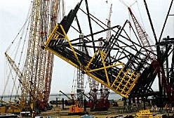
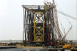
Work continues on the Virgo production platform, which is to be installed in 1,130 ft of water in the Gulf of Mexico Block Viosca Knoll 823. Once installed, only three other fixed platforms will sit at greater water depths (OGJ, Mar. 30, 1998, p. 74).The photos show the rollup of the jacket's top 640-ft section. The rollup progresses from the left to the right photo. This work took about 5 hr at Aker Gulf Marine's Ingleside fabrication facility, near Corpus Christi, Tex. Completion of the platform fabrication is scheduled for the summer of 1999. Elf Exploration Inc. operates the gas/oil/condensate project, with production expected in late 1999. (Photos courtesy of Enercon Engineering Inc.)
Copyright 1999 Oil & Gas Journal. All Rights Reserved.


