Rubbing forces provide insights into PDM wear analysis
G. Robello Samuel
EnerTech-Landmark Graphics Inc.
Houston
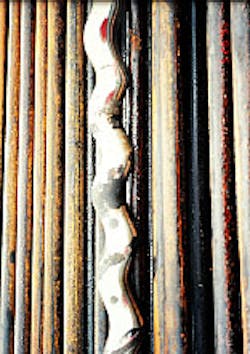
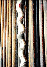
The wear on the shaft of a two-lobe motor can be clearly seen after several hours of operation. Wear is more pronounced along the seal lines (Fig. 1).The degree of rubbing intensity provides insights into the design of the power section for positive displacement motors (PDM), helping to find new ways to increase operational efficiencies.
The rubbing of the shaft against the housing elastomer results in the loss of useful power as caused by friction, leakage, swelling, and "bubble" of the elastomer. This results in troublesome wear on the housing element.
Wear effects
Wear occurs as a result of the interaction (rubbing) between the shaft and elastomeric housing surfaces. Because of the complex geometrical nature between the rubbing surfaces, a rational design of sliding contacts is required.Normally, more than one mechanism may occur simultaneously in the wear of the elements. When the shaft is not rotating, the contacts between the shaft and housing elements occur along the seal lines (Fig. 1). Then, as the shaft begins to rotate, the seal lines also begin moving, tracing along the entire housing element surface.
Therefore, the shaft seal lines continuously rub the housing surface. Thus, the number of seal lines influences the amount of wear, the speed of rotation, and the forces acting at the seal contact points.
The volume of the worn out material is given by:
Although wear caused by corrosion and friction is important, typically, the amount of wear, as compared to the wear caused by abrasion and fatigue, is not high for elastomer and metal contacts. 1Thus, the wear caused by corrosion and friction is not included in the present study. It has been observed that the abrasive and fatigue wear types normally accompany elastomer-metal combinations.
Assuming that the volume of the housing element to be rubbed and worn away is a linear function of the rubbing distance at a particular time, the amount of worn volume can be shown by:
Fig. 2 [21,061 bytes] shows the various dimensions as mentioned in Equation 2. For the time rate of volume wear, the following equation can be used: Then, allowing to be the thickness of elastomer worn, it can be shown that: Next, differentiating with respect to time, it can be found that: Thus, Equation 3 becomes: Subsequently, Equation 6 can be rearranged as follows: However, the following equation can also be used: Allowing the substitution of Equation 8 into Equation 7 we obtain:Rate of wear
For a 2/3 winding ratio motor, the housing surface at a particular point will be rubbed at twice the rotary speed of the rpm of the shaft. For a multilobe motor with an n + 1 winding number rotating at N rpm, the housing element will be rubbed (n + 1)N times.Therefore, the time rate of housing element removal, in terms of volume, for the multilobe motor will become:
It is assumed that the depth rate of wear is directly proportional to the stress at the point of contact with In addition, assuming the rate of wear is uniform throughout the housing element positioned along different angles of the shaft's position, it is assumed that wear along different angular positions will become directly proportional to the maximum stress at the point of contact. 2Thus, using:
Then Equation 11 becomes:Stress
The shaft and housing element cause a compressive contact stress as the shaft rolls. Contact stresses are functions of the shaft and housing geometry, material properties of the housing element, shaft surface treatment, and the acting forces.A large magnitude of cyclic contact stresses will cause excessive wear. Consequently, physical deterioration occurs on both the engaged surfaces, becoming much more conspicuous than what is seen in the weaker material. This results in further leakage and the loss of efficiency.
Several mathematical models have been proposed by researchers to calculate the contact stresses. Because of the sliding velocity, the elstohydrodynamic effect present in the housing element alters the stress distribution. Dynamic loading coupled with the vibratory force of the drillstring alters the stress at the contact points.
It is reasonable to model the contact stress using the Hertzian elastic compliance approach for calculating this stress. The maximum compressive stress at the point of contact between the housing element and the shaft element is given by:3
Then substituting Equation 13 into Equation 12 yields: In addition, the force (F n) acting on the contact point needs to be evaluated.Eccentricity
Fig. 3 [31,110 bytes] shows the components of force acting on the housing of a three-lobed motor. The shaft's mass eccentricity will cause a radial force (F r) on the shaft. In addition, the fluid pressure causes a pressure thrust (F p) on the shaft, which further contributes to the force applied to the contact points. The shaft will then transmit this rotating centrifugal force to the contact points of the housing and shaft element.Relatively small amounts of mass eccentricity in the shaft can cause unacceptable or even dangerous levels of contact forces at critical speed. The radial force is given by:
This radial force will be carried by the contacts throughout when the shaft rotates.The force caused by the fluid pressure is given by:
Where the surface area in which pressure is acting as found by For multilobed motors, the pressure force can by found with: And the resultant force acting at the contact point for multilobe motor is given by: Then, substituting Equation 18 for Fn into Equation 13 yields: The above equation can be further used to calculate the time rate of volume wear as follows:Rubbing intensity
In order to quantify the degree of rubbing wear, a term called "rubbing intensity" is defined. The rubbing intensity (RI) is the product of force at the contact point of the shaft multiplied by the housing element and the linear surface extent of the seal line that is being rubbed.This is expressed mathematically as:
For a multilobe motor of (n + 1) seal lines the rubbing intensity is given by:Rubbing element softness
It is possible to make either one of the rubbing elements softer than the other element, with different results. For example, if the housing element is softer than the shaft element, the housing element will wear out faster than the shaft element and vice-versa.If the housing element is softer than the shaft, the rubbing intensity is given by:
However, if the shaft element is softer then the housing element, the rubbing intensity is calculated with the following equation: The ratio of rubbing intensity of the shaft to housing is: However, Thus, the rubbing intensity of the housing is times that of the shaft.Fig. 4 [64,610 bytes] shows the plot of the rubbing intensity of wear on the housing to that of the shaft. It is evident from the plot that up to a 4/5 winding ratio motor, is more than that of the shaft.
After that, the change is not appreciable and the impact on the selection of harder material of the housing or shaft may not influence the rubbing intensity.
Therefore, for a lower pair motor, up to a winding ratio of 4/5, it is advantageous to have the shaft material softer than the housing element. The shaft would then become the first material to be destroyed, making it easily replaced as compared to that of the complex housing element.
Above the 4/5 winding ratio, both the housing and shaft element become more complex, eliminating the considerable benefits that would otherwise occur by switching the materials.
References
- Burvell, J.T., and Strang, C.D., "On the Empirical Law of Adhesive Wear," Journal of Applied Physics, Vol. 23, 1952.
- Cornell, R.W., "Compliance and Stress Sensitivity of Spur Gear Teeth," ASME Mechanical Design, April 1981.
- Meriam, J.L., Kraige, L.G., Engineering Mechanics-Dynamics, John Wiley & Sons, New York, 1992.
The Authors
G. Robello Samuel is a principal technologist II with EnerTech of Landmark Graphics Corp. in Houston. Samuel holds a BS degree in mechanical engineering from the University of Madurai in India and an MS degree in mechanical engineering from the College of Engineering Guindy, Madras. He also holds MS and PhD degrees in petroleum engineering, both from the University of Tulsa. Samuel has over 9 years of field experience and worked as an executive engineer (drilling) at Oil & Natural Gas Corp. of India.
Stefan Miska has been a professor and chairman of the department of petroleum engineering at the University of Tulsa since 1992. He holds a PhD (1973) and an MS (1968) from the University of Mining & Metallurgy in Cracow.Miska also worked at the University of Trondheim-Norwegian Institute of Technology, and at the New Mexico Institute of Mining & Technology where he became professor and chairman of the Petroleum Engineering Department.
Copyright 1999 Oil & Gas Journal. All Rights Reserved.


