Liquid-ring vacuum compressors stabilize Oman crude
Hiren Sarma
Petroleum Development Oman
Muscat, Oman
Liquid-ring vacuum compressors (LRVC) placed in upstream oil production facilities in Oman have stabilized the true vapor pressure (TVP) of crude.
Petroleum Development Oman (PDO) installed the LRVCs in two Oman facilities in 1994. This is considered to be the first such units placed in any of Shell Oil Co.'s upstream hydrocarbon-processing installations.
Liquid-ring vacuum compressors, also known as vacuum pumps, have been used in various chemical-processing industries for almost 100 years.
In the petroleum sector, although LRVCs combined with steam ejectors have gained acceptance in the downstream refining industry for the last 10-15 years, this equipment has not found much use in upstream facilities.
This author was involved in the feasibility study, preparation of the LRVC specifications, and in selecting, commissioning, and operating this equipment.
NOCS facilities
The North Oman crude stabilization (NOCS) facilities consist of two processing plants, one at Fahud and the other at Qarn Alam. The facilities were commissioned during the third quarter of 1994.
The plants have operated satisfactorily since and are delivering stabilized crude of 86 kPa absolute (12.5 psia) at the coastal Mina Al Fahal (MAF) tank farm, while increasing the NGL recovery by up to 1,000 cu m/day.
Pre-NOCS operations
Prior to the NOCS, it was not possible to directly control the true vapor pressure (TVP) of the combined oil streams from North and South Oman.
Crude TVP varied, depending on:
- Temperature difference between Oman's interior and coast
- Dehydration heater operations in the larger South Oman production stations
- NGL stabilization plant operations at various interior locations.
Recorded data indicated that TVP occasionally increased to above 100 kPa absolute (14.5 psia), endangering the safety of the MAF floating-roof tanks.
Supported by an SIPM safety audit in 1991, PDO decided to take measures for controlling the TVP of crude.
Project objective
The NOCS project's objective was to provide a crude-oil stabilization and NGL recovery plant at Fahud (Fahud CSP) to treat the North Oman crude and a vacuum flash plant at Qarn Alam (Qarn Alam VFP) to treat the South and the Central Oman crude.
This would then result in:
- Positive TVP control of the total Oman crude
- Improved NGL recovery from various interior fields
- Reduced atmospheric flaring at interior locations.
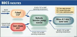
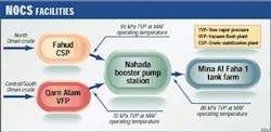
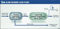
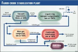
Fig. 1(at right) shows the relative locations of the two plants in the interior and the MAF terminal on the coast. Figs. 2 and 3 outline the basic process plants in Qarn Alam and Fahud, respectively.
LRVCs selection
The front-end design of the NOCS project considered the installation of API 617 centrifugal compressors for creating a vacuum in the crude separators. However, during the detailed engineering phase, the contractor, Petrofac/Galfar JV, proposed the LRVC alternative.
Because of substantial cost savings (overall savings of about $3 million) and the simpler operation of these units, the project team decided to consider this option in further detail.
Subsequently, a PDO team comprising of members from the engineering, operations, and rotating equipment group was organized to review the LRVCs' feasibility for the NOCS project.
After a preliminary in-house review, the team visited manufacturing/packaging shops, refineries, and paper mills in Europe to gain first-hand information on operations and maintenance. The use of LRVCs was supported, subject to the following conditions:
- Using proper construction material
- Including double mechanical seals
- Using water as a liquid-ring media
- Having proper equipment and accessories packaging
- Limiting the operating pressure range to 50-kPa absolute suction and to 400-kPa absolute discharge.
The medium capacity-range units were preferred. This led to the selection of two 100% Nash Engineering Co. (NASH) units in Qarn Alam and three 50% NASH units in Fahud.
The units were selected based on the available industry standards and the Eemua (Engineers Equipment & Materials Users Association) Publication No. 151.
LRVC principle
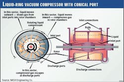
The liquid-ring vacuum compressor (pump) is, in principle, a type of rotary positive-displacement machine. Gas compression, while creating vacuum at the suction, is performed by the liquid ring formed because of the relative eccentricity between the casing and the rotating impeller (Fig. 4).
The rotating liquid ring recedes from the hub on the suction side because of the centrifugal force. This creates a vacuum and draws in the gas through the suction port.
On the pressure side, the liquid ring approaches the hub again and forces the compressed gas out through the discharge port.
System configuration
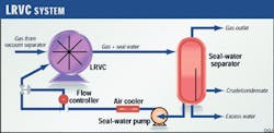
The complete LRVC system including the seal liquid (potable water in NOCS) arrangement is shown in Fig. 5. A part of the seal-water volume in the casing is continuously discharged along with the gas.
A three-phase separator separates the gas, seal water, and any condensed or carried-over hydrocarbon.
The discharged water has to be continuously replaced. This determines the seal-water circulation rate for the system.
The LRVC compression can be considered to be isothermal because of the small increase in temperature (5-10° C.). The main functions of the operating liquid in an LRVC system are to:
- Remove compression heat
- Maintain a stable liquid ring
- Effectively seal the axial clearances between the impeller and the casing.
A closed-loop, seal-water system is used and an air-cooler cools the discharged water from the separator before returning it to the compressor.
Important features
The following factors were included in the LRVC system:
- Stainless steel for the LRVC, seal-water separator (SS clad), and associated piping
- Maintenance of the liquid level in the LRVC (centerline) by aligning the LRVC discharge with the seal-water separator liquid level and making it a permissive for LRVC start-up. Permissive means satisfying an event before the next event can occur. In the LRVC logic sequence, the LRVC will not start until the recycle valve is open, minimum seal-water flow is established, and the liquid level is established in the seal-water separator.
- Safeguards for shutting down the unit because of minimum seal-water flow, low vacuum in the suction, and high differential pressure across the LRVC
- A double mechanical seal instead of standard stuffing box
- An auto start-up logic with built-in permissive that provides ease of operation.
Mechanical seal system
Although stuffing-box packing is a common seal in many LRVC industrial applications, John Crane double mechanical seals were recommended for the NOCS plants because of sour hydrocarbon gas.
The double-seal arrangement combines two mechanical seals installed back to back in the stuffing box. A barrier fluid (pure water) is circulated from a reservoir through the seals at a pressure above the stuffing-box pressure and then back to the reservoir.
A cooler is provided on the returning stream to prevent fluid from overheating.
The original seal system was designed to circulate fluid by a thermosiphon effect. During commissioning, a thermosiphon system was found to be ineffective. It resulted in leakage because of improper circulation of barrier fluid that prevented the fluid from removing the heat generated between the seal surfaces.
The seal design was then modified to a forced-circulation system with a pumping ring. This stopped seal leakage.
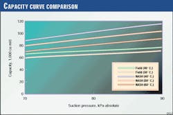
Fig. 6 shows the capacity curves from field trials at Qarn Alam plant plotted against the manufacturer's curves.
The curves show the increase in compressor capacity as the seal-liquid temperature decreases. This is attributed to precondensation of saturated gas at a lower temperature.
The difference in capacities is attributed mainly to the lack of proper measuring devices in the field. The calculations used the opening percent of the control valve.
The following important design features should be examined carefully before designing any LRVC system:
- A suction/discharge differential pressure (DP) high-alarm trip for protecting the LRVC. Sufficient margin should be provided between the operating DP, alarm DP, and the trip DP to avoid any undesirable alarms and trips.
- The LRVC seal-liquid (water in the case of NOCS) piping configuration should be designed carefully for proper operation. This is particularly important for parallel operation of two or three units.
While operating two units, if one of the units trips, the circulating seal water may enter the operating unit, causing high-level trip in the seal-water separator.
This can be avoided by properly designing the piping system so that the seal water from the tripped unit is distributed immediately to the seal-water storage system.
LRVC future
The NOCS LRVC units have been operating successfully with minimum maintenance for over 4 years.
PDO should examine the possibility of using LRVCs for flare-gas recovery. It should be noted that as the first units in upstream hydrocarbon processing, considerable design margins in metallurgy, mechanical seal system, etc. were used in selecting the NOCS LRVC units.
For flare-gas recovery, low cost, off-the-shelf units are considered adequate.
A single-stage, 4:1 compression ratio unit would be sufficient to supply the discharge gas to the standard PDO low-pressure gas grid system.
