Italian land rig exploits small reserves
Dean E. Gaddy
Drilling Editor
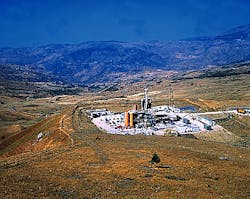
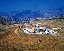
On location in Italy's Po Valley, the G-125 drill rig can be set up on pads as small as 30 x 30 m. Conventional rigs require locations about 70 x 90 m in size (Fig. 2). Photo courtesy of Saipem.
A new land-rig design allows Italian operators to exploit reserves of limited size, allowing economic development of reservoirs containing only a few hundred million cu m of gas.
- Both the G-125 and G-200 drill rig handles all drilling and casing tubulars from a vertical position, eliminating the need for horizontal pipe racks, catwalks, and v-doors (Fig. 3). Photo courtesy of Saipem.
- Both the G-125 and G-200 (shown) drill rigs utilize a top-drive system. Conceptually, the driller handles the drillstring similar to a snubbing unit, utilizing push-pull forces instead of a block and tackle for pipe movement (Fig. 5). Photo courtesy of Saipem.
- The driller controls the drillstring while monitoring drilling parameters from a self-contained cabin. The console contains alarm systems that provide a safer working environment (Fig. 6). Photo courtesy of Saipem.
Production rates for these small prospects, located in North Italy's Po Valley in southern Italy, and in Sicily, are typically 20,000-70,000 cu m/day.
Prior to the highly mobile, semi-automated G-125 drilling unit, built by Soilmec SpA and contracted by Saipem SpA, low margins for ENI-Agip SpA prohibited development of these small fields using standard rigs. Bruno Pini, project manager for Saipem, said "Marginal fields are profitable only if overall costs are less than $650/m. The scope of the G-series rig project was to reduce this cost by 25-30%."
The G-125 prototype rig, built with partial funding from the Thermie European Community program, has drilled 18 wells since July 1996 (Fig. 1 [136,981 bytes]), saving ENI-Agip 24% in total drilling costs and 30% in drilling and moving time.
Overall, average penetration rates increased from 7.5 to 35 m/hr and from 75 to 300 m/day. In addition, nonproductive time fell from 450 to 120 hr/well, including operations that involve BOP, casing, and cementing activities.
According to Pini, "Based on the best performance in the area (Po Valley) achieved with a conventional rig, drilling time took 309 hr to reach TD. However, a 2,500 m well has been drilled with the G-125 in only 190 hr."
The newer G-200 drilling unit, built and delivered last December, incorporates numerous improvements over the G-125.
Nevertheless, both rigs are designed to:
- Improve mobility for quick and frequent rig moves
- Increase penetration rates
- Reduce wastes, noise, and civil works
- Minimize footprint and visibility (Fig. 2)
- Reduce personnel
- Enhance safety.
Vertical pipe racking
The G-series rigs incorporate an innovative vertical pipe-racking system that surrounds the substructure in a semicircular pattern (Fig. 3). Twelve containers, each of which holds drill pipe and collars, ranging from 8 to 31/2-in. OD, provide enough storage to drill over 3.5 km.The multisized tubulars are handled along the peripheral edge of the rig and back and forth to the drill floor using a 6-metric ton jib crane fitted to the rig. Two persons are normally required to handle tubulars, although in case of emergencies, one is sufficient.1 A second jib, mounted next to the doghouse, provides additional handling capabilities.
During pipe connections, extending and tilting braces allow the top drive to connect up single joints positioned within the mouse hole. To operate the vertical pipe-racking system, drill pipe or casing is taken from individual vertical chambers and set in the mousehole using a joy stick-actuated jib (Fig. 4 [128,499 bytes]).2 The mousehole accommodates various tubular lengths using a hydraulic clamp that suspends each joint at the proper height. Typically, each pipe section is 40-ft long.
When it comes time to add a new section, the top drive moves out from the well center until it is positioned vertically over the mousehole. The top drive then makes up with the mousehole tubular, bringing it back to the well center so it can be added back to the drillstring.
Because the portable pipe-racking chambers allow for preloaded pipe transportation, inspection and preparation procedures are minimized. In addition, because the tubulars are set back in individual chambers during trips and drilling, the mast and rig floor do not require a monkey board and racking mat, further reducing the size of the mast and rig substructure.
Hydraulic systems
The hydraulic components of the G-200 are packaged in a self-contained configuration that never requires disassembly. A hydraulic cylinder, bolted to the skid-mounted trailer, operates the top drive and telescoping mast, reducing its height and weight and making transportation on standard roads as a single piece possible.In Italy, the G-200 and G-125 drill rigs do not require transportation permits as do conventional 1,000-hp rigs. During rig moves, the number of loads are reduced to 30, normally taking 5-6 days; as compared to 40 loads for 1,000-hp conventional rigs, requiring 10-12 days to move and rig up.
In addition, the hoisting system eliminates the need for massive structures required in most block-and-crown assemblies, further reducing size and visibility. When fully raised, the 16-m mast does not require wind bracing.
The top drive is hung from four cables that engage sheaves mounted on top of the hydraulic cylinder (Fig. 5).1 This arrangement allows a maximum tripping velocity of 1 m/sec.
Four hydraulic motors power the top drive, capable of 3,600 kg-m of torque at 60 rpm. The maximum pull-down capacity for the hoist is 20 metric tons, while the maximum static hook-load capacity is 181.5 metric tons (G-200).
Because the rig uses a pull-push system for moving, slowing, and parking the drillstring, standard band brakes-a major cause of rig noise-are eliminated, reducing noise levels to less than 6.2 db during drilling operations. This is especially important for operating the rig in highly populated areas.
Four hydraulic pistons lower and raise the 6.1 m substructure. Altogether, it takes about 45 min to raise both the substructure and mast.
Automation and personnel
Automatic drilling can easily be achieved through a pre-set penetration rate or by application of a constant torque setting, controlled by the driller from the control panel (Fig. 6). The alarm system is embedded with the block-control system so that drilling operations can be safely and quickly shut down.Predetermined values of overpull and torque can be set to prevent the accidental damage of drill pipe during stuck-pipe situations. On-line data acquisition displays real-time information on the driller's console and in the toolpusher's office.
Automation has led to a reduced number of personnel. On a daily basis, the G-series rig requires a toolpusher, motorman, electrician, and roustabout. For each shift, the rig requires a driller, assistant driller, and derrickman, eliminating the need of two floorhands normally needed on conventional rigs.
The rig can independently perform casing jobs using a special hydraulic device fitted to the top drive for make-up procedures. Casing can be run in the hole and filled with mud at the same time. In addition, the rig contains a bulk cement surge along with two batch-mixer tanks. A 200 cu m mud/water system is fully integrated into the rig equipment consisting of three mud tanks.
Equipment
The G-200 rig is equipped with the following components.- Four 700-kw, Caterpillar sound-proof diesel-electric generators and Siemens power control room
- Automatic hydraulic slips and 11,000 kg-m power tong
- One power swivel (0-200 rpm)
- One 11 in. x 5,000 psi annular Hydril GK BOP
- One 11 in. x 5,000 psi Cameron D single blind/shear ram BOP
- One 11 in. x 5,000 psi Cameron U dual-ram BOP
- One 135/8 in. x 3,000 psi diverter spool
- Two primary Mass 1,000-hp pumps
- One standby Soilmec 600-hp pump rated at 600 hp
- Two dual Brandt shale shakers
- One degasser and centrifuge.
References
- Schenato, A., Calderoni, A., Grandi, M., and Cesaroni, R., "Innovative Approach in Slim Hole Drilling," SPE paper 29925 presented at the International Meeting on Petroleum Engineering, Beijing, Nov. 14-17, 1995.
- Pini, B., and Marcellini, F., "G-125: An Innovative Hydraulic Drilling Rig for Marginal Field Development: Field Experience," SPE paper 49481 presented in Abu Dhabi, Oct. 11-14, 1998.
Copyright 1999 Oil & Gas Journal. All Rights Reserved.

