B.V. Samoilov
Transnefteproduct
Moscow
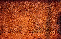
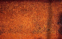
Corrosion pits cover the internal surface of a refined-products pipeline (Fig. 1).
- A special pump truck has pulled along the pipeline right-of-way to pressurize a refined-products pipeline for hydrostatic testing (Fig. 2). [24,937 bytes]
- Hydrostatic testing ruptured this products pipeline (Fig. 3). [22,784 bytes]
- A coiled length of pipeline explosive awaits installation of a segment of line to be cut (Fig. 7). [13,041 bytes]
- Workers have just finished installing lengths of explosive cord on a segment of line to be cut out and replaced (Fig. 8). [25,149 bytes]
- The same segment of pipe after explosive cutting awaits further repair (Fig. 9). [25,175 bytes]
- Acoustic emission (results on one analysis shown here0 is an important tool in ensuring the integrity of Transnefteproduct's system (Fig.5). [31,488 bytes]
The tools are extremely sensitive to such contaminants in the line as corrosive solids attached to the pipe wall or any other type of debris.
Aging system
Transnefteproduct operates more than 12,000 miles of refined-product pipelines. One third of these lines is very old: the 112-mile Ishimby-Ufa, 62 years old; the 727-mile Ufa-Omsk, 47 years old; the 582-mile Ufa-Petropavlovsk, 44 years old; and the 428-mile Omsk-Sokur, 41 years old.Despite regular surveillance, there is still a possibility of a pipeline being damaged without knowledge of the operator. The causes are mostly material and construction defects.
Cathodic protection and rehabilitation prevent active external corrosion of refined-product pipelines. Internal corrosion, however, has proven to be the more difficult problem. Causes are mainly the presence of water, gas, and oxidants.
In mountainous regions, water accumulated at the lower sections of the line can be removed only when the line is pigged. For example, the pigging of the Ufa-Omsk in 1994 removed 28 metric tons of water and 20 metric tons of debris.
Samples of debris were collected from the slugs of water. Analysis of it indicated the presence of corrosion products. The corrosion pits on internal surface of pipe are shown in Fig. 1.
Geometrical and mechanical defects, either from manufacture and pipe laying or from third-party damage during service, can sometimes lead to structural weakening of the pipelines. In order to check and maintain the integrity of Russian product pipelines, in-line inspection is required.
External inspection
Because of the size or pipe configuration, not all Russian products pipelines can be inspected internally. Hydrostatic testing, widely used for reconditioning of old pipelines, uses special equipment to increase the pressure (Fig. 2).Cutting out of a cylindrical piece of pipe and replacing it with pipe of similar or greater strength usually repairs ruptures caused by hydrostatic testing (Fig. 3).
Hydrostatic testing has for many years been considered the only way to assess pipeline integrity. It is generally expensive, however, and requires the pipeline to be shut down.
Moreover, it gives only a "Go/No go" evaluation and does not allow locating of anomalies so long as they do not lead to leaks or ruptures. Very localized defects, such as pits, cannot be detected because their depths can penetrate practically the entire wall thickness without leak or rupture. As a result, other methods of inspection have been successfully used.
Acoustic-emission (AE) testing is a method for examining the behavior of pipeline steel deforming under stress. The AE method represents the diagnostic tool for inspecting structures and integrity control of pipelines that cannot be inspected by in-line inspection tools.
AE may be defined as a transient elastic wave generated by the rapid release of energy within a material. Steel "talks" when it is in trouble: with AE equipment you can "listen" to the sounds of cracks growing and many other modes of active damage in the stressed pipeline steel.
Because small-scale damage is detectable long before failure, AE can be used as a nondestructive technique to find defects during structural proof tests of a pipeline. Plastic deformation, crack initiation, and crack growth from fatigue or corrosion, all give rise to AE signals.
Unlike for other nondestructive testing methods, the energy converted to AE signals comes from the material itself. Since the acoustic signals from defects radiate throughout the structure, relatively few transducers are needed to detect and qualify defects over a large area. AE is used for testing that requires periodic assurance of structural integrity of Russian pipelines.
For AE, piezoelectric sensors are evenly spaced along the pipeline (Fig. 4 [56,360 bytes]). The pressure-test procedure consists of basic stress-strain calculation of pipeline, determination of maximum level of inner pressure, and controlled increase of inner pressure in a pipeline.
For practical application on the pipeline, it is necessary to increase inner pressure carefully. Test-load pressure levels are: starting load, increasing load, intermediate hold, and decreasing load. The sound waves from defects in a pipeline are collected by piezoelectric sensors and analyzed by computer-based algorithms.
After continuous measurement of acoustic-emission data, the results of intensity analysis for each pipeline section between two sensors are plotted (Fig. 5).
Evaluation criteria for Russian pipelines have been developed over years. These are based on experimental laboratory data, destructive tests of pipelines, and experience gained from field tests.
Of particular importance are field test case histories that correlate AE data with detailed nondestructive follow-up examination of the pipeline.
Evaluation criteria are based the following:
- Emission during load hold
- Number of counts for a specific increase in load
- Number of events up to previous maximum operating load, number of events above previous maximum operating load, and total events
- Number of large-amplitude events
- Measured area under the rectified signal envelope or events amplitudes as a function of stress
- Total activity as a function of stress.
- Grade 1: Major defect requiring immediate shutdown and follow-up nondestructive examination.
- Grade 2: Significant defect requiring immediate follow-up inspection using complementary nondestructive examination methods.
- Grade 3: Defect requiring follow-up evaluation. This evaluation may be based on further data analysis, retest, or complementary nondestructive examination.
- Grade 4: Note for reference in future tests and check for surface defects such as corrosion, pitting, gouges, or cracked attachment welds.
- Grade 5: Minor defect; note for reference in future tests.
Inspection detected internal corrosion produced by accumulation of water at low points as a result of intermittent reductions of flow velocity and even due to some flow stoppages. The moderate anomalies were inspected, confirmed, and cut out.
Even if these tests are useful, corroded areas can go undetected, especially in the case of buried pipelines, which constitute the major part of the length of pipelines.
In-line inspection
In-line inspection of pipelines using the so-called "intelligent pigs" is increasingly the solution for evaluating the structural integrity of Russian pipelines. This tool can indicate changes in pipe-wall thickness and the presence of corrosion craters and defects.As a complement, metal-loss inspection pigs detect, locate, and gauge anomalies, such as gouges. But the pipeline must have launch-and-receipt facilities and must allow free passage of the pig.
Parts of Russian refined-products pipelines cannot accommodate intelligent pigs because of physical limitations such as pig traps or reduced-bore valves or other fittings. An operator must consider the design of his pipeline to determine whether a pig can be used.
The first metal-loss in-line inspection operation on a Russian products pipeline was carried out in 1995 and used a Pipetronix Ultra Scan tool. This inspection was used to evaluate the extent of different defects of a 20-in. OD, 110-mile pipeline.
Installed in 1971, this pipeline transports refined products from the Bashkirian Republic refineries to the Russian Western regions. The first inspection for metal loss by magnetic-flux-leakage system was carried out in 1997 on a 20-in. OD, 133-mile pipeline.
Those inspections and others were used to evaluate the extent of different defects. The scope of work for in-line inspection includes pipeline preparation and launching of in-line inspection tools. Pig launchers and receivers were prepared for in-line inspection tools.
As with any form of in-line inspection, pipeline internal surface preparation is of paramount importance. The quality of preparation directly affects the integrity inspection.
Product residue should be cleaned from the pipeline internal surface. Trans nefteproduct adopted pipeline pigging as a routine cleaning operation. Slugs of water, however, were always received in front of each pig, indicating that the major part of the water was separated in the line as a result of low velocity.
The pipeline was cleaned in readiness for metal loss in-line inspection. A progressive schedule involves different types of pigs: cups pigs, brush cleaning pigs, various sizes of gauging plates, and magnetic pig-tracking equipment.
The first pig to be run through the line was a cups pig. When it was received, it was pushing the remains of different large debris.
Its removal paved the way for the progressive cleaning program, starting with basic gauging runs to check for dents and geometric obstructions. After just a few runs, it was apparent from repeated damage to the gauging pig's measuring plates that progress of the enhanced cleaning tools would be prevented.
A caliper pig was therefore used to establish the location of geometric obstructions that turned out to be pipes with large dents and valves with reduced bores.
Cutting out the damaged section and replacing it required the line to be taken out of service. Valves with reduced bores were repaired on-line in service. Once repaired, the line was run with enhanced cleaning pigs in final stages of the inspection program.
Pushed by refined product at a velocity of 1 m/sec, the tool gave useful indications on laminations and metal loss of pipe wall.
Inspection results; digs
The survey gave accurate measurements of pipe-wall losses and locations. The on-line survey report for the refined-products pipeline Ufa-West on the Cherkassy-Subkhankulovo segment with total length of 110 miles indicated 151 suspected defects and damage sites on the pipe.The results included 60% geometrical defects, 20.6% laminations, 12.6% metal loss (pits, craters, or grooves), and 4.5% inclusions. Distribution of the metal-lamination indications along the pipeline was shown on a histogram (Fig. 6 [55,222 bytes]).
Following receipt of the on-line survey report, a predetermined number of suspected defects (at varying distances, orientation, and altitude along the entire pipeline) were selected for excavation and inspection for confirmation of the integrity of the pipeline.
Verification digs were conducted and residual thickness of the pipe wall was determined with ultrasonics. The results given by inspection with spot external measurements were acceptable. Inspection detected important lamination areas.
Calculations of all stresses and the maximum allowable operating pressure of defective pipe used PCs and software based on finite-elements method.
A computerized process was used to grade the metal-loss features according to their estimated depths. Part of the engineering work on the pipeline consisted of a detailed study of the acceptable operating pressure for the line.
Pipeline lengths showing suspect defects were systematically examined, and a program of repair of defective sections was established after the survey. Defects in pipelines found by these techniques were inspected in accordance with Russian refined-products-pipelines criteria and, depending on severity, accepted without repair, dressed out, or removed and replaced with new pipe.
Repair options were evaluated from economic and safety points of view. This repair program can take immediate action to reduce risk of a failure on the more laminated and corroded areas. This step involves elimination of all corroded areas exhibiting 20% or more reduction in thickness and large laminations.
Repairs methods
Requirements and standards of repair methods are prescribed in "Code for repair of ruptures and imperfections of refined products pipelines" approved in 1997 by the Russian Ministry of Fuel and Energy.The selection of pipeline repair methods depends on the type and extent of damage and overall condition of the affected pipe material.
In general, repairs fall in three categories:
- Repairs of nonleaking pipeline due to internal and/or external corrosion or mechanical damage
- Repairs of leaking pipeline
- Repairs of ruptured or deteriorated pipeline sections.
Directly deposited weld material is an old technique used to repair wall loss, scratches, and gouges. Weld overlay should be ground smooth to the original pipe wall surface.
Welded patches are primarily used for the repair of localized corroded small areas of the pipe. Even when not used over leaks, patches create severe stress concentrations at the toe of the fill welds where they lie perpendicularly to the hoop stress. Welded repair sleeves are either butt-strap or butt-weld type.
Repair methods for leaking pipelines include steel plugs, weld caps, welding rings, repair clamps, bolted split sleeves.
Steel plugs are used for sealing off a pit tip leak prior to placing a sleeve. Tapered steel pipe-repair plugs will normally extend into the bore of the pipe and damage the cups of pipeline pigs.
Therefore, steel plugs are not used on lines designed to be scraped unless the tip of the plug is cut so that after installation, it will not protrude more than 1/8 in. inside the pipe.
Alternatively, the plug projection can be sawed-off and a patch applied. But this entails the risk of leakage during welding, and the use of a patch is not recommended.
Weld caps can be used over repair areas up to 3 in. in diameter. Weld caps are 1-ft long sleeves fabricated with a corrugation primarily to accommodate the repair of leaking girth welds. They can also be used as sleeves for leaks and corrosion repair.
Welding rings are proprietary repair clamps that have been used to a limited degree on high-pressure pipelines. To complete the repair, a pipe cap is placed over the elastomer-sealed area and welded to the pipe. Welding the cap permits the subsequent cutting of the strap.
Split sleeves are costly compared to other methods of pipeline repair. Therefore their use should be restricted to those cases for which speed of repair will provide sufficient economic justification. They are particularly attractive for permanent repair of small holes and ruptures which cannot be plugged readily and for which downtime for draining refined product from a line is excessive.
The repair of ruptured or deteriorated pipeline sections includes weld plus end couplings and clamp sleeves. The common application involves cutting out a corroded length of a pipe and replacing it with a new pup piece of pipe. Weld plus end couplings are expensive and should be used only when economics dictate.
The technique used is to place the couplings over the pipe ends and slip them over the other half, anchor the coupling in place, and then seal it in the pipeline. These couplings are incapable of high-pressure axial loads before weld-out.
Clamp sleeves are designed as pipe couplings. They counteract end pull and axial stresses encountered in installation. The clamp ring surfaces grip the outside pipe wall.
Repairs involving leak clamps or split reinforcement shell are generally regarded as temporary expedients only, and sectional replacement is carried out as soon as the system is shutdown and excavation permits. Before repair work is carried out, it may be necessary to limit the pipeline operating pressure to enable the work to be done safely.
The last option requires a pipeline shutdown, although temporary repairs using encirclement fittings are sometimes acceptable.
Versatile equipment and improved technology continue to be developed in this area. For example, the segment of pipeline for replacement could be taken out of service by an explosive charge with a concave shape.
Such a cord (Fig. 7) contains an explosive charge pressed around the outside of a sheet-copper cone. A copper-covered explosive cord that has a V-cross section will cut a pipe-wall metal when detonated. The cord is useful for separating parts of oil and refined-products pipelines.
Such cuttings require digging up the pipeline, setting the ring of an explosive charge on the pipe, filling the trench with soapy-water foam to prevent fire, then setting off the explosion (Figs. 8 and 9).
The explosion takes the form of a high-velocity jet with the capacity to cut the pipe wall. After the trench is dug, it takes only a few minutes to do the cutting with a circumferential explosive charge with a concave shape.
The Author
B.V. Samoilov is a department head for Transnefteproduct, Moscow, a position he assumed in 1994. He began his career in 1964 as a senior engineer of an oil-product storage facility in Siberia and, in 1967-1974, was a senior researcher and chief of the pipeline-maintenance laboratory at the Scientific Research Institute of Oil Transport in Ufa.In 1975, Samilov became chief of computing laboratory, Scientific Research Institute of Automatic Control in Pipeline Construction in Moscow, moving to senior researcher and associate professor of the Moscow Academy of the Gubkin Institute of Oil and Gas where he remained until 1981. That year he became chief of the scientific center of oil and gas transportation, National Institute of Hydrocarbons and Petrochemistry, Boumerdes, Algeria. In 1983, he became associate professor, later professor, Moscow Academy of the Gubkin Institute of Oil and Gas.
Samoilov holds a Diploma Mechanical Engineer (1964), Ufa Petroleum Institute, Ufa, and Doctor of Sciences Diploma (1977), Moscow Academy of the Gubkin Institute of Oil and Gas.
Copyright 1998 Oil & Gas Journal. All Rights Reserved.


