New waste-heat refrigeration unit cuts flaring, reduces pollution
Benjamin Brant, Sabine BrueskePlanetec Utility Services Co. Inc. and Energy Concepts Co. (ECC), with the help of the U.S. Department of Energy (DOE), developed and commissioned a unique waste-heat powered LPG recovery plant in August 1997 at the 30,000 b/d Denver refinery, operated by Ultramar Diamond Shamrock (UDS).
Planetec Utility Services Co. Inc.
Evergreen, Colo.Donald Erickson, Riyaz Papar
Energy Concepts Co.
Annapolis, Md.
This new environmentally friendly technology reduces flare emissions and the loss of salable liquid-petroleum products to the fuel-gas system.
The waste heat ammonia absorption refrigeration plant (Whaarp) is the first technology of its kind to use low-temperature waste heat (295° F.) to achieve sub-zero refrigeration temperatures (-40° F.) with the capability of dual temperature loads in a refinery setting. The ammonia absorption refrigeration is applied to the refinery's fuel-gas makeup streams to condense over 180 b/d of salable liquid hydrocarbon products.
The recovered liquid, about 64,000 bbl/year of LPG and gasoline, increases annual refinery profits by nearly $1 million, while substantially reducing air pollution emissions from the refinery's flare. Fig. 1 [15,861 bytes]shows the installed refrigeration skid.
Project development
The Whaarp project was implemented as Phase II of a four-phase master efficiency plan developed by Planetec in cooperation with refinery engineers and managers. The master plan is a comprehensive process optimization and utility efficiency program to maximize energy savings and productivity while minimizing pollution and generation of greenhouse gases.With support from Oak Ridge, Argonne, and the National Renewable Energy Laboratories, DOE provided technical assistance and shared in one-third of the $2.3 million capital cost to design and build this demonstration project. In addition, DOE used the refinery-efficiency program as a showcase model for its Climate Wise and Motor Challenge programs.
Refinery audit
The master plan and Whaarp project were based on a detailed refinery-wide audit conducted by Planetec, ECC, and their team of engineers and consultants. As a result of the audit, a number of areas of inefficiency were discovered.One of these areas involved the loss of petroleum products in the refinery fuel-gas system. A substantial amount of salable product (C3-C6+) is commonly present in fuel-gas makeup streams which are routed to the refinery fuel-gas header. Fuel gas is used by the refinery as the primary energy source for fired heaters and boilers.
During the summer months when cooling of the reformer effluent is limited, considerable excess fuel gas is produced and therefore flared. This results in the loss of salable LPGs and gasoline, as well as the needless generation of flare emissions.
The net gas and treat gas streams in the reformer unit contribute significantly to the loss of salable products to the fuel-gas system. The recycle-gas compressor recycles a hydrogen-rich gas stream within the reformer unit to the reformer reactors to provide hydrogen to the reactors.
Part of the hydrogen-rich gas stream produced in the reformer unit is sent to the Whaarp unit for LPG recovery. Leaving the Whaarp unit, a portion of this stream, referred to as "treat gas," is routed to the naphtha hydrotreater (NHT) as makeup hydrogen, while the remainder of this stream, referred to as "net gas," is directed to the fuel-gas system.
The NHT desulfurizes the naphtha feed to the reformer unit. A substantial amount of C3+ material contained in the net gas and treat gas streams is lost to the fuel system, about 2.5 bcf/year.
Fig. 2 [28,957 bytes]is a simplified diagram of the reformer unit. The diagram identifies the locations of the waste-heat tie-in and the net/treat gas stream where the Whaarp unit is located.
Mass-integration techniques, heat-pinch analysis, and simulation tools were used to determine the best strategy to debottleneck the reformer effluent condenser and recover salable material from the fuel-gas system. From these analyses it was determined that refrigeration was the best approach to meet both objectives.
Mass integration was used to identify the fuel-gas stream with the greatest concentration of recoverable C3+ material. The stream with the highest recovery potential was the reformer net/treat gas stream. Simulation analysis indicated that by cooling the net/treat gas stream to a temperature of -25° F., 45% of the C3+ material would be recovered.
Initially, the refinery considered the option of purchasing an electric-powered ammonia screw-compressor refrigeration skid from another refinery. After a detailed evaluation, however, it was determined that the compressor skid would cost an additional $175,000/year in energy and require greater maintenance. Furthermore, the mechanical chiller would not be capable of cooling more than one temperature load simultaneously.
"We could have installed the standard compressor-driven refrigeration skid," says Steve Sondergard, UDS refinery manager, "but we decided to push the envelope and install this new waste-heat-driven unit. It has allowed us to work with some of DOE's national labs learning several best practices and energy-efficient techniques."
Process description
The absorption refrigeration cycle differs from a conventional compression-refrigeration cycle in that a waste-heat powered reboiler (or generator) and absorber function in place of an energy-intensive, electric-driven compressor. Fig. 3 [55,288 bytes] is a simplified vapor-liquid equilibrium diagram for the Whaarp cycle, illustrating temperature, pressure, and composition.The technology is based on a simple design using low-temperature waste heat from a refinery process stream to generate refrigeration. Waste heat is supplied to the system at 295° F. from the reformer reactor effluent.
The Whaarp unit is sized to deliver 85 refrigeration tons at -31° F. for net gas/treat gas cooling, and 180 refrigeration tons at 26° F. for other intermediate temperature applications, which have yet to be determined. Other potential refinery cooling applications include the fluid-catalytic cracking (FCC) wet-gas compressor inlet vapor, the FCC unit sponge-absorber lean-oil stream, trim-cooling fractionator-overhead streams, vacuum-unit vacuum jets, and the FCC-regenerator air-blower inlet.
The Whaarp unit was designed with a coefficient of performance (COP) of 0.5.
The Whaarp unit comprises two distinct loops: an absorbent loop and a refrigerant loop. The absorbent is an ammonia/water mixture with concentrations varying from 15 to 50% ammonia, and the refrigerant is 99.9% ammonia with a minimal amount of water.
Fig. 4 [50,627 bytes] is a simplified process flow diagram for the system. As indicated in the figure, the absorbent flows in a loop between the rectifier and the absorbers, and the refrigerant flows in a loop between the rectifier overhead, the condenser, the chillers, the absorbers, and back to the rectifier/reboiler.
Two pressure levels are achieved by the 295° F. waste heat, with a low-pressure absorber serving the low-temperature chiller, and an intermediate-pressure absorber serving the intermediate-temperature chillers. The following key equipment make up the Whaarp unit:
- Rectifier. Feed to the four tray rectifier column is a weak absorbent from the low pressure and intermediate-pressure absorbers. The function of the rectifier is to fractionate weak ammonia-water absorbent into ammonia-vapor refrigerant in the overhead and strong absorbent liquid in the bottoms of the rectifier.
- Reboiler. The rectifier bottoms stream passes through the thermosyphon reboiler which partially vaporizes the strong absorbent providing reboil to the rectifier column. Heat is provided to the reboiler by exchange with the waste-heat stream from the reformer unit.
- Condenser. Ammonia vapor from the rectifier is condensed in the evaporative condenser, and an ammonia level is maintained in the receiver.
- Chiller. In the chiller, heat is transferred to the liquid ammonia from the process stream, thereby evaporating the ammonia and chilling the process stream. The ammonia refrigerant vapor proceeds to the absorbers, and the process stream proceeds to a separator where the liquid product is recovered.
- Absorber. Ammonia vapor effluent from the chillers and the strong absorbent from the rectifier bottoms are combined and cooled to form weak absorbent. Aqua (20% aqueous ammonia solution) passes through the absorbers to remove the heat generated by absorption. The weak absorbent is pumped to the rectifier to complete the cycle.
An automated digital control system (DCS) is used to regulate and monitor the performance of the unit. Thirty separate temperature, pressure, flow, and level sensors instantaneously transmit data and alarms to a central control room.
Operational performance
The Whaarp unit has been operating since Aug. 5, 1997. Two key improvements have been made to the unit since initial start-up. During the last week in October, the unit was shut down for modifications to improve the vapor injection mechanism of the absorbers.A fabrication error was also corrected on the rectifier tower trays. These two modifications improved the performance of the unit by reducing the chiller temperature by over 40° F.
Fig. 6 [39,920 bytes] shows the performance curves for chilling the net/treat gas stream following the modifications.
The LPG recovery rate varies considerably over time (Fig. 6). This can be directly attributed to changing ambient temperatures and the operation and loading of the reformer unit. As mentioned earlier, the recovery rate increases during the summer months of operation when reformer effluent cooling is decreased and there is a greater percentage of salable product in the stream.
The project economics are based on the recovery of salable products. Laboratory gas chromatography readings of the liquid product stream indicate that during the summer months, about 70% of the product is gasoline (i.e., C5, C6+). These heavier gasoline products generally have a significantly higher dollar value than LPGs (C3, C4).
Environmental, economic benefits
Due to the recovery of salable product from the refinery fuel-gas system, the amount of flared fuel gas is substantially reduced. This not only saves money and reduces wasted energy, it lowers emissions from the refinery flare and refinery heaters and boilers.Table 1 [9,303 bytes] outlines the criteria pollutant and CO2 greenhouse gas emission reductions for the Whaarp unit. Criteria pollutants (CO, NOx, SO2, PM10, volatile organic chemicals) are reduced by over 26 tons/year, and CO2 emissions are reduced by over 9,500 tons/year.
Although the capital cost of the Whaarp unit is higher than an equivalent mechanical refrigeration unit, it has the added benefit of a greatly reduced electrical operating cost. Table 2 [10,543 bytes] outlines the final economics of the project at the UDS Denver refinery.
The Authors
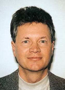
Benjamin Brant is founder and president of Planetec Utility Services Co. Inc. He has 25 years of experience in the energy and environmental fields as an engineer, a systems integrator, an innovator, and a pioneer in the industry. Brant has received two National Energy Innovation Awards from the DOE and has authored four bills in the Colorado State Legislature related to energy and water efficiency. Brant holds a BS in environmental design from the University of Arizona, Tucson, with honors and a masters degree in urban/regional planning from the University of Colorado, Denver.
Sabine Brueske is a process engineer for Planetec Utility Service Co. Inc. She has 5 years' experience in industrial facilities, military installations, and manufacturing plants. Brueske holds a BS in chemical engineering and petroleum refining, with a minor in environmental science and engineering, from Colorado School of Mines, Golden, Colo.
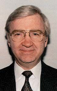
Donald Erickson is founder and president of Energy Concepts Co. (ECC). He is responsible for directing research and development activities in the areas of absorption refrigeration and heat pump technology at ECC. Erickson is the recipient of 60 U.S. patents and numerous national and state technology awards. Erickson holds a BS in naval science from the U.S. Naval Academy, with graduate studies in chemistry, chemical engineering, and mechanical engineering at the University of North Carolina, Chapel Hill, and George Washington University, Washington D.C.
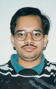
Riyaz Papar is a senior project engineer at Energy Concepts Co. (ECC). He specializes in two-phase heat transfer enhancement techniques for refrigerants. He is the lead engineer for ECC in the product design of prototypes and full-scale systems. Papar is a registered professional engineer in the state of Maryland and holds an MS in mechanical engineering from the University of Maryland, College Park.
Copyright 1998 Oil & Gas Journal. All Rights Reserved.
