World's longest sulfur pipeline operating smoothly after 3 years
Graeme G. King
Greenpipe Industries Ltd.
CalgaryJ.E. Lawrence, John J. Baron
Shell Canada Ltd.
More than 3 years of trouble-free operation on the world's longest liquid-sulfur pipelines have affirmed the attention to detail and the early engineering effort that solved the problems of transporting liquid sulfur in a buried pipeline at temperatures greater than 120° C.
Careful engineering and project planning led to completion on time and under budget of the 41 km (24.6 mi) long line.
Sulfur is extracted from sour gas at Shell Canada Ltd.'s Caroline gas plant, Alta. It is carried cross-country as a liquid to the nearest railhead to the south.
The pipeline is built from two coaxial pipes. The inner pipe carries liquid sulfur, while the annular space between the inner and outer pipes carries circulating hot water under pressure. A return line completes the loop for the circulation of hot water.
The system employs two water heaters, one at each end of the line. It can carry continuously up to 5,100 tons/day (t/d) of liquid sulfur.
The route winds through hilly terrain in the foothills of the Rocky Mountains and crosses under three major rivers.
Discovery
In 1986, Shell discovered a large reservoir of sour gas in the foothills of the Rocky mountains near Caroline, Alta. Preliminary planning began immediately for a gas-processing plant to produce sweet natural gas, condensate, and sulfur.
Community consultation resulted in a decision to locate the gas plant near Caroline and to transport sulfur as a liquid to an existing railhead at Shantz (Fig. 1 [22106 bytes]). There, the sulfur would be pelletized and loaded into rail cars for shipment to Vancouver where it would be sold on the international market.
A buried pipeline was chosen at the preliminary planning stage. It was more environmentally acceptable than new rail or road construction and was preferred by local residents. It was also cost competitive with the alternatives.
Conceptual design of the pipeline began in 1989 with the development of design philosophies for alternative methods of heat tracing, insulation, construction, and operation.
The pipeline was to carry 4,500 t/d of liquid sulfur and be expandable to 8,000 t/d to accommodate potential future production from other nearby fields. The system was to be able to remelt sulfur that solidified in the line in the unlikely event that it had to be shutdown without purging.
Shell demanded high reliability because the Caroline gas plant could not be operated without the capability of shipping sulfur.
The most economic and practical solution that finally emerged called for a pipe within a pipe. The inner pipe would carry liquid sulfur; the annular space would circulate hot water under pressure. A return line would complete the loop for the continuous circulation of hot water.
The entire 41 km of pipeline would be heated with only two water heaters, one at each end of the line.
To prevent the pipe from pushing through the ground at bends due to thermal expansion at high operating temperatures, deep burial, high backfill compaction, and very long-radius bends were used. The pipe was also preheated to "stretch" it during construction.
High density polyure thane foam that could transmit shear stresses between the pipe and the backfill insulates the lines. The insulation is protected by a tough, high-density polyethylene jacket.
Detailed design began in 1990 with preparation of final drawings, right-of-way acquisition, and construction planning. Laboratory tests of a full-scale prototype were conducted in early 1991 to ensure nothing had been overlooked in the structural design work.
The pipeline was built in summer and fall 1991 and commissioned with hot water in summer 1992. Liquid sulfur began flowing in early 1993 and the pipeline has operated successfully since.
Flow properties, equations
There is nothing unusual about the flow properties of liquid sulfur in the range of interest for a buried pipeline, that is, between temperatures of 120° C. and 150° C.
Outside that range, sulfur has many interesting properties. For example, it normally melts at 118.9° C. but solidifies at 114.5° C., and it exhibits unusual properties at temperatures near 158° C.
Density, viscosity, and specific heat of liquid sulfur over the range of interest for a buried pipeline are shown in Fig. 2 [78898 bytes].1
Typically, liquid sulfur is twice as heavy and about as viscous as many light oils that are commonly carried in oil pipelines. Pressure loss (DP) along the pipeline and sulfur pumping power (W) can be calculated with normal hydraulic equations shown in Equations 1 and 2 in the accompanying equations box.
Heat transfer (Qg) from the soil through the insulation2 and flowing temperature (T) can also be calculated from standard equations (Equations 3 and 4).
Finite difference versions of Equations 1-4 were used in the design work. (The effect of heat-tracing fluid has been omitted from Equation 4 for clarity of illustration.)
Engineering and cost studies showed that a pipe 219.1 mm (8 in.) OD was the optimum size to meet design flow requirements. The sulfur pumps needed a power of 200 kw and a flow capacity of 105 cu m/hr.
Hot-water heat tracing
Conceptual design favored hot-water heat tracing over electrical heat tracing for the buried sulfur pipeline. Investigations showed that hot water heat tracing:
- Could remelt sulfur without bursting the pipe
- Required minimal surface facilities along the route
- Required minimal field work to remain operational
- Allowed immediate detection of pipeline leaks
- Reduced rate of sulfur cooling during shutdown.
The route for the sulfur pipeline winds through rolling foothills of the Rocky Mountains and crosses under three major rivers. There are, therefore, many sag-bends and over-bends along the route.
Unlike water which expands by about 9% when it freezes, sulfur contracts almost 9% when it solidifies. If sulfur stops flowing for any reason and solidifies inside the pipeline, it gravitates to the sag-bends as it contracts.
During remelt, the opposite occurs. If the sulfur remelts unevenly along the line and traps sections of melted sulfur between plugs of solidified sulfur, it can burst the pipe.
Hot-water heat tracing automatically remelts the line from one end only, making it easy to ensure that the sulfur has somewhere to flow as it expands and thereby preventing dangerous buildup of pressure.
With electrical heat tracing, on the other hand, it can be difficult to obtain a uniform remelt particularly in the vicinity of cable pull-boxes and other irregularities in the cable or the pipe.
It was also discovered during conceptual design that hot-water heating systems could be designed with very long distances (more than 100 km) between heater stations. This meant that the sulfur pipeline could be built without surface facilities along its 41-km length.
By contrast, electrical heat-tracing systems would require four or five power-input and transformer stations along the route.
Another advantage of hot-water heat tracing was the minimal amount of field work required to keep hot-water heat tracing systems operational. By contrast, electrical systems use heating elements that burn out periodically.
Pull-boxes with specially designed surface facilities every kilometer or so along the route are needed to replace burned-out cables. Pulling burned-out cables from buried conduits can still be difficult, particularly if the cables weld to the conduit when they fail.
Leak detection is also easier with hot-water heat tracing. Because the water jacket and return line form a closed loop, any leak in the sulfur carrier, water jacket, or return line can be immediately detected by measuring changes in water level in the pressurized surge tanks located at the suction side of the hot-water pumps.
The final advantage of hot-water heat tracing resulted from the extra heat capacity provided by the water. If the system is shutdown for maintenance, the pipeline cools more slowly, allowing extra time for work to be completed before the sulfur begins to solidify.
Optimization of alternative heat tracing systems favored annular hot-water heat tracing. Fig. 3 [65850 bytes] shows a schematic of the chosen system. It has two hot-water loops, with a heater at each end of the line. At low sulfur flow rates and during remelt, both heater stations are needed.
During remelt, the Shantz heater station has valves and piping that allow the direction of hot-water flow in the Shantz loop to be reversed. In this case, the Shantz station takes water from the return line, heats it, and pumps it directly into the annulus at the Shantz end.
The hot water flows through the annulus to the intermediate valve station and returns directly to Shantz through the return line.
The intermediate valve station was designed to allow the two loops to be connected into one single loop.
Under normal flow conditions, when the system is operated as a single loop, water enters the annulus at Caroline and flows the full length of the line to Shantz. At Shantz, the water enters the return line and flows back through the intermediate valve station to Caroline.
Heaters were sized so that, at design sulfur flow rates, the entire 41-km length of both the sulfur and hot-water return lines could be maintained at design temperature with only one heater station located at either end of the line.
Heater duty (Qw) to maintain steady-state flowing conditions was found from a simple energy balance by summing the heat lost to the surrounding environment from all elements of each loop and by subtracting the power required by the water pumps (Ww) as well as the heat contribution to the system of the flowing sulfur (Equation 5).
Design work showed that the optimum diameter of the water jacket was 323.9 mm (12 in.) and the optimum thickness of polyurethane foam insulation was 80 mm.
Optimum diameter of the hot-water return line was 168.3 mm (6 in.) with 50 mm of polyurethane foam insulation. Optimum water flow was 162 cu m/hr and water pump power was 336 kw.
The water heaters had a capacity of 3,300 kw each. With heaters of this size, it is possible to remelt the entire line with both heater stations in approximately 100 hr after a protracted shutdown in which the sulfur cools to ground temperature.
Design options
Operation at high temperatures to keep sulfur as a liquid causes thermal expansion of the pipe steel. Structural design work looked at several alternatives for accommodating this expansion:
- Construction of pipes inside a buried conduit to allow free movement of the pipe
- Buried expansion loops to allow partial movement of the pipe
- Long-radius bends and high backfill compaction, fully to restrain the pipe.
Engineering studies showed that the third alternative would also require preheating to "stretch" the pipe during construction. The preheat would keep thermally induced stresses in the steel within allowable limits and reduce forces exerted by the pipe on soil at bends.
Engineering studies also indicated that the third alternative would be the most reliable and would require the least maintenance. Cost estimates showed it required the least capital.
It was subsequently chosen as the construction method for the liquid sulfur pipeline.
When a pipeline is fully restrained and operated at high pressures and temperatures, failure of the pipe wall is a problem because hoop tension and longitudinal compression both act in the same direction on the shear plane.
The Tresca failure criterion predicts that failure begins when the sum of longitudinal compression and hoop tension exceeds the yield strength of the pipe steel in shear.
The Canadian code3 that governed design and construction of the sulfur pipeline limited hoop stress to 72% of the specified minimum yield strength (SMYS; Equation 6) and limited combined stress from temperature effects and internal pressure to 90% (Equation 7).
Combined stresses were kept to less than 90% SMYS by an increase in wall thickness and preheating during construction.
Final design work selected a wall thickness of 8.2 mm for the sulfur carrier pipe, 6.4 mm for the water jacket, and 4.8 mm for the return line.
Pipe anchorage
If soil fails at a bend in a buried pipeline operating at high temperatures, large uncontrolled pipe movements can cause plastic deformations of pipe steel and possible pipe failure.
Large movements of the pipe through the soil can also damage insulation and tear its protective jacket, resulting in water degradation of insulation and corrosion of pipe steel.
High temperature differentials, therefore, make it important to prevent large movements from occurring.
The total axial force (F) that needs to be restrained at a bend is the sum of the forces due to temperature differential, Poisson's ratio, and the axial force from internal pressure (Equation 8).
If the pipeline is fully restrained so that no movement occurs at the bend, static equilibrium between soil restraining forces (w) at the bend and axial forces in the pipe (F) predicts the minimum radius (Rmin) that can be restrained by the soil at a bend (Equation 9).
Calculation of soil-restraining strength (w) is not straightforward. It varies with time of year and has different values for sag-bends, side-bends, and over-bends.
Soil along the route of the liquid sulfur pipeline consists largely of clay till which has little cohesive or frictional strength during spring break-up.
At that time of year, the restraining force of the backfill at over-bends, for example, results largely from soil weight. In this case, the restraining strength of the soil (w) can be approximated by Equation 10.
Well-compacted backfill is obviously important at bends to prevent pipe from pushing through the soil, but it is also important in straight sections between bends.
Good compaction in straight sections increases bond between pipe and soil and reduces the possibility of large movements that could kink the pipe if soil inadvertently failed at the bend.
Specifications therefore called for sand to be well compacted around the pipes before backfilling with native clay till.
Long-radius bends were implemented by grading the right-of-way before stringing and ditching began. The right-of-way layout resembled an expressway with gradual side-bends, over-bends, and sag-bends. A specialized grading program was developed for the purpose.
For buried insulated pipelines, shear stresses resulting from thermally induced movements of the pipe relative to the soil are transmitted through the insulation. High-strength polyurethane foam that could withstand the high shear stresses and that could bond to the polyethylene jacket and the steel pipe was therefore specified.
Long-term heat exposure tests were performed at 155° C. to prove that the insulation could maintain its thermal and structural integrity at high operating temperatures.
Longitudinal movement of the sulfur-carrier pipe as a result of thermal expansion and self-weight through the hilly terrain was prevented by anchoring of the inner pipe to the outer pipe every kilometer or so with a specially designed forging. The forging was designed to restrain the ultimate axial load capacity of the sulfur carrier pipe.
Optimization work using carefully selected worst-case scenarios selected a minimum depth of cover of 2.0 m and a minimum bend radius of 140 m. This is sufficient to prevent the pipe from moving at bends when the maximum differential between construction and operating temperature is 70° C.
Since the maximum operating temperature of the pipeline had been set at 140° C., the minimum allowable preheat temperature was 70° C.
Prototype tests
Laboratory tests of full-scale prototypes were undertaken to make sure that nothing had been overlooked during structural design work.
Several test specimens were prepared. Each specimen consisted of a 16-m long joint of 8-in. sulfur-carrier pipe and 12-in. water jacket pipe.
Prototypes of centralizers were used to keep the sulfur carrier centered inside the water jacket. Blind forgings, identical to the forgings that would be used to anchor the sulfur carrier to the water jacket during construction, were used to anchor the sulfur carrier to the water jacket at each end of the prototype assembly.
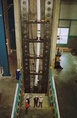
The entire joint of coaxial pipe was then loaded in a 20-m high press (Fig. 4 - see below) that could put the joint in axial compression and tension to simulate thermally induced stresses that the sulfur pipeline would experience in practice.

Sulfur carrier pipe and water jacket are positioned for full-scale testing (Fig. 4).
Hydraulic rams were mounted laterally on the water jacket so that the prototype could be bent laterally at the same time that it was put into axial tension or compression. The annular space was connected to a positive-displacement pump so that it could be pressurized.
The prototype assembly was instrumented with displacement gauges and strain gauges. The general sequence of full-scale prototype testing was as follows:
- Deflect pipe laterally into a 90-m radius bend with no axial load to simulate pipeline construction with a preheat temperature of 90° C.
- While still holding the pipe in a 90-m bend, tension the pipe to simulate cool-down to 0° C.
- Hydro-test the annulus to 12.9 MPa at 0° C.
- Axially compress the pipe and pressurize the annulus to 9 MPa to simulate operation at 160° C.
- Cycle axial load and annular pressure to simulate temperature and pressure fluctuations over the lifetime of the project.
At the end of the first test, the specimen was pressurized and axially compressed to simulate a hydro-test of the annulus at 13.5 MPa with a temperature increment of 160° C. (that is, a case with zero preheat). No evidence of buckling or collapse appeared in either pipe.
The full-scale prototype tests provided experimental validation of the adequacy of the design to resist stresses during construction, pressure testing, and subsequent operation, including cool-down and remelt cycles.
Preheating
Buried pipelines can be pretensioned by heating them during construction and by backfilling the trench and completing the tie-in welds while the pipe is still hot.
Apart from permitting thinner walls and lower-strength steels, preheating reduces axial compression and reduces the force on surrounding soil at bends. That decreases depth of burial required to restrain the pipe, or alternatively, allows the use of tighter bends.
Thinner walls, lower strength steels, shallower burial, and tighter bends all reduce costs and more than offset the cost of preheating.
Water and air were both investigated during design. Air was chosen as the preheat medium because it is easier and safer to use during construction.
The mass flow of air required to heat pipe depends on such factors as pipe steel mass, acceptable heating time, and rate of heat loss from the pipe.
It can be calculated from the energy balance of the system by equating the rate of build up of heat within the pipeline to the difference between the net convective heat energy flowing into the system and the conductive heat energy flowing out of the system through the insulation.
A centrifugal compressor with a design flow of 1.9 standard cu m/sec (4,000 scf/min) powered by a 250 kw (335 bhp) diesel engine was used to generate the hot air. Maximum design discharge pressure was 85 kPa(g).
Discharge-air temperature was controlled at 110° C. by varying suction and discharge pressures slightly and by drawing a variable mixture of ambient air and engine cooling air into the suction of the compressor.
Since the objective was to heat the pipeline to an average temperature of 90° C., a discharge temperature of 110° C. was ideal and additional heating or cooling equipment was unnecessary.
Air from the compressor was fed into a discharge header fitted with four separate butterfly valves so that air flow to the different pipes in the trench could be regulated individually as required.
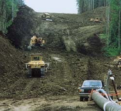
Right-of-way is cleared in the Canadian Rocky Mountains foothills (Fig. 5).
Construction
The right-of-way was graded (Fig. 5 - above) to limit the minimum bend radius along the right-of-way to 140 m. The 8-in. sulfur carrier was fitted with centralizers and pulled into the 12-in. water jacket at a remote site.
The coaxial pipe assemblies were then delivered to the right-of-way as needed and were strung on skids alongside the return line.
The sulfur carrier was welded first. After each sulfur carrier weld had passed inspection, the water jacket was moved into position and welded. After each water jacket weld had passed inspection, a polyethylene sleeve was fusion-welded to the polyethylene casing.
The polyethylene sleeve and fusion weld were pressure tested before a hole was drilled in the sleeve and polyurethane foam was cast in place over the water jacket weld.
Because of the frequency of road, pipeline, and river crossings, it was convenient to divide the pipeline into sections which ranged in length between 0.3 and 1.4 km. Anchor forgings were welded in place to secure the sulfur carrier to the water jacket at each end of each section.
A parallel sequence was followed for the return line. After each return line weld had passed inspection, a polyethylene sleeve was moved into place and fusion-welded to the casing.
After the polyethylene sleeve and fusion weld had been pressure tested, a hole was drilled in the sleeve and polyurethane foam was cast in place over the return line weld.
The new section of coaxial assembly and section of return line were then lowered into the same trench.
The next step was to heat the pipes overnight. The coaxial assembly was heated first by blowing air through the sulfur carrier as well as through the annulus. The compressor had enough flow capacity to heat the longest section of coaxial pipe in less than 6 hr.
After heating the coaxial section, air flow through the sulfur carrier was diverted to the return line. While the return line was being heated, air flow was maintained through the annulus to keep the coaxial assembly hot.
The return line could be heated in less than 6 hr while still maintaining the temperature of the coaxial pipes.
Thermal expansion was checked the next morning. If growth was insufficient, the pipes were recradled and lifted slightly by a side-boom tractor to break friction with the ground and to allow the pipes to expand freely. Backfill operations began while air still flowed through the pipes.
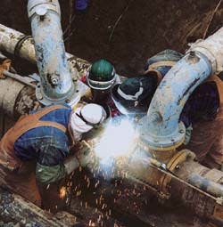
Tie-in welding proceeds on the 8-in., sulfur-carrier pipe while preheat air flow through the annulus is maintained (Fig. 6).
Tie-in welds between the previously backfilled section and the newly heated section (Fig. 6 - above) were completed while backfilling proceeded. A small amount of 110° C. air was first blown back through the annulus and return line of the previous section to reheat the exposed ends before welding began.
The tie-in weld on the sulfur carrier pipe was completed, inspected, and passed before the air compressor was shutdown and disconnected. The tie-in weld on the return line was completed next and the split sleeve tie-in weld of the water jacket was made last.
Polyethylene sleeves were fusion-welded to the insulation casings of both the water jacket and the return line and polyurethane foam cast in place over the welds. The bell-hole at the tie-in weld was then backfilled.
Operation
The sulfur pipeline has normally carried 4,600 t/d with excursions as low as 1,200 t/d and as high as 5,100 t/d. It was shutdown for 2 weeks during plant turnaround in 1995. During the turnaround, the hot-water heat tracing system was kept in full operation.
Typically, the hot-water heat tracing system is operated as a single loop. The sulfur carrier takes sulfur at a temperature of 145° C. from the plant at Caroline. Heat-tracing water from the return line enters the water jacket at Caroline at 120° C.
The sulfur and the heat-tracing water reach Shantz at 122° C. The sulfur flows to tanks and the heat-tracing water returns to Caroline in the return line. At Caroline the water is pumped to pressure and heated to 120° C. for delivery back to the water jacket.
Within 1 km from Caroline, the heat-tracing water and sulfur reach an equilibrium of 130° C. The maximum temperature experienced by the polyurethane insulation is therefore 130° C. which is within its allowable long-term operating temperature.
When sulfur flow rates fall below 3,500 t/d, it is necessary to operate the hot-water heat tracing system as two separate loops in order to keep the delivery temperature at Shantz greater than 120° C. and the maximum temperature of the insulation less than 130° C.
Resistive wires were embedded in the insulation during fabrication and construction for leak detection. At several locations, minor variations in readings from the resistive wires have implied that water may have permeated the insulation.
Routine observation of water levels in the surge tanks ruled out the possibility of a leak in the water jacket. Digs and visual inspection of the polyethylene casing were therefore undertaken. No defects in the casing were found.
A base level of fluctuation in readings from the resistive wires has therefore been accepted. No increase in fluctuations greater than the base level has occurred to trigger further investigation of possible water infiltration.
The right-of-way has been inspected routinely and no evidence of soil movement has been observed.
Acknowledgments
The authors wish to acknowledge contributions of Shell Canada Ltd., EPC contractor SNC-Lavalin Inc., construction subcontractor Parkland Oilfield Construction (1983) Ltd., structural testing laboratory Centre for Frontier Engineering Research, materials-testing laboratory Shell Canada Research Centre in Calgary, and insulation applicator Tarco Energi A. S.
They would also like to acknowledge the innovative ideas of many who made the project successful, in particular, R.A. Wahlstrom of Shell Canada Ltd., N. Lenstra of Nikann Enterprises Ltd., and Mario Tonini of Shell Chemicals.
References
1. Tuller, W.N. (ed.), The Sulfur Data Book, New York: McGraw-Hill, 1954.
2. Carslaw, H.S., and Jaeger, J.C., Conduction of Heat in Solids, Clarendon: Oxford, 1946.
3. Canadian Standards Association, Z183-M90, Oil Pipeline Systems, CSA: Rexdale, 1990.
The Authors
Graeme G. King is vice-president of engineering at Greenpipe Industries Ltd., Calgary. He was previously a principal design engineer for SNC-Lavalin where he undertook design and construction inspection work for Shell's liquid sulfur pipeline. King holds a BS (1964) and an MEngSc (1970), both in civil engineering from the University of Sydney, Australia. He is a registered engineer in Alberta.
J.E. (Ted) Lawrence is a project coordinator at Shell Canada Ltd. He was a project engineer on Shell's Caroline Project, working on both the gas plant and the sulfur pipeline. He holds a BE in mechanical engineering from McGill University in Montreal and is a registered engineer in both Alberta and Ontario.
![Equations [47697 bytes]](http://images.pennwellnet.com/ogj/images/ogj2/95036201.gif)
![Fig. 1 [22106 bytes]](http://images.pennwellnet.com/ogj/images/ogj2/9503jki01.gif)
![Fig. 2 [78898 bytes]](http://images.pennwellnet.com/ogj/images/ogj2/95036001.gif)
![Fig. 3 [65850 bytes]](http://images.pennwellnet.com/ogj/images/ogj2/95036101.gif)
John J. Baron is head of nonmetallic materials engineering for Shell Canada Ltd. He was the nonmetallic materials specialist for Shell's Caroline Project, working on the field gathering system, gas plant, and sulfur pipeline.Baron has a diploma in petroleum technology from the Southern Alberta Institute of Technology, Calgary. He is chairman of the CSA Plastic Pipe Task Force and of the NACE
International Membership Committee.
Copyright 1997 Oil & Gas Journal. All Rights Reserved.