New ammonia process, catalyst proven in Canadian plant
Anne K. Rhodes
Refining/Petrochemical Editor

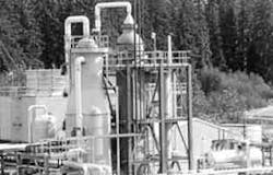
Pacific Ammonia Inc.'s ammonia plant in Kitimat, B.C., is the first commercial installation of M.W. Kellogg's KAAP and KRES processes. The two large columns shown here are the KRES unit autothermal reformer (left) and reforming exchanger (right).
Pacific Ammonia Inc. (PAI) has increased ammonia production 40% at its Kitimat, B.C., plant. The retrofit that enabled it to do so was the first commercial application of two new ammonia technologies.
The reduced-energy ammonia synthesis process uses a new, noniron catalyst. The addition of a reforming exchanger produced the additional synthesis gas that boosted ammonia production.
PAI, formerly Ocelot Ammonia Co., completed the first phase of the retrofit in late 1992. This project involved adding a new radial-flow ammonia converter and precious-metal catalyst, both licensed by M.W. Kellogg Co., Houston.
Phase 2 of the retrofit was the addition of a reforming exchanger system to reform natural gas feed. This unit uses process heat to eliminate the fired, primary reformer.
The combination of the two technologies increases energy efficiency by recovering heat at a much higher temperature.
Plant history
The Ocelot plant was commissioned in 1986 with a capacity of 544 metric tons/day (mt/d). It incorporated Kellogg's reduced-energy ammonia technology and used purge gas from Methanex Corp.'s adjacent 1,250 mt/d methanol plant as feedstock.
In 1992, Ocelot converted the plant to the Kellogg Advanced Ammonia Process (KAAP) technology. KAAP enabled the plant to maintain 100% of its operating capacity while decreasing steam usage 30-40% and electricity consumption 5-10%.
Japan's Mitsui & Co. purchased the plant from Ocelot in 1994. PAI is a wholly owned subsidiary of Mitsui.
In 1994, PAI added a new Kellogg Reforming Exchanger System (KRES). The new reformer increased production of synthesis gas at the plant's front end and boosted ammonia production by 40% to 780 mt/d.
KAAP technology
According to Kellogg's product manager, Stan Knez, the KAAP catalyst is the first important advance in ammonia-synthesis catalyst technology since iron catalyst was introduced more than 80 years ago.1
KAAP uses a ruthenium-based, copromoted catalyst supported on a graphitic structure. The catalyst was developed by Kellogg and BP.
The catalyst's activity is as much as 20 times greater than that of traditional ammonia catalysts, says Knez. It maintains its high activity at relatively low temperatures and pressures, and at high ammonia concentrations.
The catalyst is manufactured by Engelhard Corp., Iselin, N.J., under license from Kellogg.
PAI installed its KAAP unit downstream of the existing magnetite converter (Fig. 1 [21908 bytes]). The two-bed, hot-wall KAAP reactor features a low pressure drop and radial flow (Fig. 2 [17998 bytes]).
![Fig. 1 [21908 bytes]](http://images.pennwellnet.com/ogj/images/ogj/9447jrh1.gif)
![Fig. 2 [17998 bytes]](http://images.pennwellnet.com/ogj/images/ogj/9447jrh2.gif)
Because of the KAAP catalyst's high activity, thin beds are necessary to keep operating temperatures within the prescribed range.
In most radial-flow reactors, the upper portion of the bed is sealed with excess, unutilized catalyst. This prevents feed gas from bypassing the reaction section when the catalyst settles.
Kellogg's reactor uses a proprietary sealing system. This technology avoids the catalyst maldistribution that can lead to formation of hot spots in the catalyst bed. The system also enables 100% of the loaded catalyst volume to be utilized for reaction.
KRES technology
The KRES process uses a unique configuration to replace the fired reformer (Fig. 3 [14084 bytes]). This is possible because heat from the autothermal reformer is used to achieve a portion of the reforming.
![Fig. 3 [14084 bytes]](http://images.pennwellnet.com/ogj/images/ogj/9447jrh3.gif)
In the proprietary, open-tube design, catalyst-filled tubes are suspended from a single tube sheet at the cold end of the exchanger (Fig. 4 [18620 bytes]). The exchanger's parallel arrangement minimizes the pressure differential across the tube sheet, according to Kellogg literature.2
![Fig. 4 [18620 bytes]](http://images.pennwellnet.com/ogj/images/ogj/9447jrh4.gif)
The tubes are typically 2.0 in. OD (50 mm) and contain conventional nickel-on-alumina catalyst. The open-tube configuration allows each tube to expand freely. It also facilitates catalyst loading and unloading.
The carbon-steel shell of the reforming exchanger is jacketed with water and lined with a dual refractory layer. The top head allows full access to the shell interior and tubesheet.
Compared to a fired reformer, the likelihood of damage to the catalyst tubes as a result of an operating upset is much less in the reforming exchanger. This is true because direct flame impingement cannot occur, and because flue gas distribution is not a concern.
The maximum temperature of the tube metal is limited to the temperature of the shell-side gases. By contrast, in a radiant box, tube-metal temperature is limited by the temperature of the combustion flue gas.
The combined KAAP/KRES process increases energy efficiency by recovering heat at a much higher temperature. Energy is freed from involuntary steam generation and used in a manner that is more efficient, thermodynamically, says Tom Czuppon, technology development manager for Kellogg.
More than 50% of the heat available in the reformer effluent is recovered and used in the reforming reaction, resulting in energy consumption as low as 23.4-24.8 MMBTU (lower heating value)/short ton, or 6.5-6.9 gigacalories (LHV)/metric ton (Fig. 4).2 These values represent a 5-10% reduction in energy consumption relative to a conventional ammonia plant.
Eliminating the burners also minimizes the process control challenge associated with the reformer and reduces maintenance and operating requirements. And the lack of a flue gas stream reduces emissions of NOx and CO2 by as much as 60-75%.3
PAI's KAAP unit
PAI's retrofitted ammonia synthesis loop operates at about 2,000 psia. Compressed fresh feed and recycle exit the compressor and are combined with compressed syngas from the KRES expansion project.
The combined streams pass through a feed/effluent exchanger. The partially heated converter feed then flows to the existing converter (labeled 105-D in Fig. 1), which uses conventional magnetite catalyst.
The effluent from this converter flows to a steam superheater, then to a steam generator. The generator produces medium-pressure (3,000 kPa) steam, which drives the feed compressor (103-J).
The gas exits the boiler and flows to the KAAP converter. The stream enters the reactor through a side inlet and is heated in the internal exchanger tubes (Fig. 2). An external bypass line around this exchanger provides first-bed inlet temperature control.
The gas flows through the first bed, then on to the shell side of the internal exchanger and to the second bed. The effluent from the second bed of KAAP catalyst is about 19% ammonia.
The effluent is cooled in a second medium-pressure steam generator. It then flows to the shell side of the feed/effluent exchanger (121-C in Fig. 1).
Shell-side effluent from this exchanger is cooled in a water exchanger (124-C), where ammonia condensation begins. A four-stage "unitized" exchanger completes the condensation process.
The ammonia is cooled to -33° C. in a two-case, centrifugal compressor. The refrigerated liquid is then removed and sent to storage.
Recycle gas is passed back through the tube side of the unitized exchanger and is returned to the last wheel of the syngas compressor. Some of the recycle gas is sent to compressors that were added as part of the KRES front-end expansion.
Because the front-end expansion is based on reforming rather than purge gas, the feed gas contains more inert materials than it did before the revamp. As a result, purge gas from the expanded plant is processed in a membrane hydrogen-recovery unit.
This unit recovers 85-90% of the hydrogen for recycle.1 Waste gas from the membrane separator is blended with purge gas from the refrigeration compressor and flash gas from the flash drum. PAI uses this combined stream as supplemental fuel.
KAAP start-up
The KAAP catalyst was loaded in the oxidized state. To activate the catalyst, the start-up team reduced it by passing fresh synthesis gas over the catalyst beds and heating them to 300° C.
KAAP catalyst generates only a small amount of water during reduction because it contains much less metals than conventional iron catalyst. For this reason, the reaction proceeds swiftly. The reduction process at PAI took only 19 hr and went smoothly. (Reduction of conventional iron catalyst takes 36-48 hr.)
Following catalyst reduction, the magnetite converter was brought on-line and stabilized. Synthesis gas was then routed to the KAAP unit.
PAI produced first ammonia from the KAAP unit in November 1992. The unit has reduced the plant's energy requirements by 0.6 MMBTU/metric ton of product.4 Steam usage has decreased 30-40%.
KAAP operation
Since start-up, the milder operating conditions have reduced pressure, recycle flow, and syngas compressor speed.
PAI has operated the unit under a wide variety of conditions and process upsets. Some changes were made intentionally, for the purpose of testing the unit. Others were the result of normal variations in operations.
In December 1993, during initiation of a planned shutdown, a large quantity of CO was inadvertently admitted into the ammonia synthesis loop for several hours. During this incident, CO concentrations reached about 4,000 ppm(vol) while the reactor was operating at near-design temperatures.
When the system was restarted, the KAAP catalyst was deactivated. Following re-reduction of the catalyst, it regained its activity over several days of operation. (The magnetite catalyst, also deactivated during this incident, regained its activity as well.)
The unit has been exposed to helium levels as high as 20% since start-up. The helium was introduced in the natural gas feed to the methanol plant.
The original KAAP design didn't include a continuous loop purge because concentrations of inert materials were expected to be low. Continuous purge for methane was installed with the KRES unit in 1994. This feature automatically removes any helium present.
The membrane-based hydrogen recovery unit added during the KRES expansion does not separate hydrogen and helium effectively. PAI has added a secondary purge which controls excess buildup of inerts. In addition, to increase plant control and stability, PAI now measures helium continuously using a mass spectrometer.
Another addition that has made unit operations smoother is using the mass spectrometer to analyze KAAP streams for hydrogen and nitrogen. This enables closer control of the H/N ratio to the loop and, as a result, consistent ammonia conversion.
PAI regularly provides KAAP operating data to Kellogg, which monitors and evaluates unit performance. Kellogg plots production rates and catalyst-bed temperature differentials to monitor catalyst activity and trends.
Fig. 5 [49543 bytes] shows the data collected during the 1-year period following KRES unit start-up.
![Fig. 5 [49543 bytes]](http://images.pennwellnet.com/ogj/images/ogj/94474001.gif)
As the preceding anecdotes illustrate, the addition of the KAAP unit has increased process flexibility. Table 1 [7276 bytes] shows comparative operating data before and after addition of the KRES unit, which constitutes a major change in KAAP process conditions, particularly gas hourly space velocity.
![Table 1 [7276 bytes]](http://images.pennwellnet.com/ogj/images/ogj/94474101.gif)
After nearly 4 years of service, the unit has shown no evidence of catalyst deactivation. Unit performance has met or exceeded all design criteria. Capacity now exceeds 820 mt/d, and the reactor has been operated at rates as high as 860 mt/d.
PAI's KRES unit
In 1994, PAI installed a new KRES reformer to convert natural gas feed to additional synthesis gas.
PAI purchased the front-end plant from C.F. Industries, Terre Haute, Ind., and relocated it to Kitimat, B.C. The 350 mt/d plant includes a reformed-gas boiler, shift converters, CO2 removal, methanation, and make-up gas compression.
Kellogg's work on the front end was limited to the reforming exchanger system (Fig. 3). Kellogg modified the existing secondary reformer with a specially designed mixing/combustion zone at the unit inlet. It is this device that eliminates the burner.
New equipment packages were installed for syngas drying and purge gas recovery.
Because PAI uses nitrogen produced by its air-separation plant to make ammonia, the waste oxygen stream from the air separator was available for enriching the air to the autothermal reformer. Enriched air keeps the H/N ratio within prescribed limits and maintains the heat balance around the reforming exchanger and autothermal reformer.
A preheated mixture of hydrocarbon and steam flows in parallel to the reforming exchanger and autothermal reformer (Fig. 3). Oxygen, steam, and a portion of the hydrocarbon are fed into the mixing/combustion zone of the autothermal reformer.
Two basic reactions take place in this unit:
- Exothermic partial oxidation of feed hydrocarbon
- Endothermic reforming of the hydrocarbon with steam.
The temperature of the autothermal reformer effluent is about 1,000° C. This stream flows to the inlet of the reforming exchanger shell.
The portion of the hydrocarbon/steam mixture not fed to the autothermal unit is fed to the tube side of the reforming exchanger. As the mixture flows through the tubes, it contacts conventional reforming catalyst.
The shell-side stream provides the heat required for the endothermic reforming reaction. This stream comprises effluent from the autothermal reformer and from the tube side of the reforming exchanger.
After the heat from these two streams is exchanged, heat is recovered from the shell-side gases via steam generation. The synthesis gas is then purified further.
KRES operation
Syngas from PAI's KRES unit was first introduced into the ammonia loop in November 1994. Performance of the reforming exchanger and autothermal reformer have been excellent since start-up.
Table 2 [11126 bytes] shows a comparison of exit-gas analyses from the autothermal reformer and reforming exchanger. The table separates the data into two periods: initial operation (1995) and subsequent operation (1996).
![Table 2 [11126 bytes]](http://images.pennwellnet.com/ogj/images/ogj/94474102.gif)
The KRES unit has been subjected to more than 40 start-up/shutdown cycles. Problems with the used equipment-in particular, the reciprocating compressors-largely were responsible for the frequent shutdowns.
The reforming exchanger proved quite durable during this unplanned test. Heat transfer in the reforming exchanger has been better than expected. This "overperformance" has permitted PAI to vary operations and improve overall system performance.
Kellogg expects some reformer fouling over time, but has seen none to date.
Methane slip exiting the reforming exchanger shell has remained at or below the design value of 0.30 mole % when running at design feedstock levels.1 System pressure drop also remains low.
For 1995, KRES pressure drop averaged 28.5 psi while the plant operated at 98% capacity. While operating at 100% capacity this year, the pressure drop has averaged 31.5 psi.
Inspection
The KAAP reactor was inspected in February 1996. Inspection of the converter revealed the unit and catalyst to be in good condition.
According to Czuppon:
- The internal heat exchanger was in perfect condition.
- All metal surfaces were clean.
- There was no evidence of corrosion or nitriding.
- The catalyst screens were in perfect condition.
- There were no unusual changes in internal tolerances.
- The catalyst bed level was as expected.
- There was no physical deterioration of the catalyst.
- The catalyst's chemical and physical properties were within original specifications.
The reforming exchanger was inspected in October 1996 and was found to be in excellent condition.
Since proving its KAAP technology at PAI, Kellogg has licensed it to two companies in Trinidad: Farmland MissChem Ltd. (a joint venture of Farmland Industries Inc. and Mississippi Chemical Corp.) and Nitrogen Leasing Co. Completion of both 1,850-mt/d units, each valued at $240 million, is scheduled for early 1998.
Kellogg says the capital costs of grassroots KAAP/KRES plants are about 10% less than those of conventional ammonia plants. The savings are mainly the result of reduced pressure in the synthesis loop, which allows for use of a simpler, single-case compressor.
A number of KAAP retrofit projects for capacity expansion also are under construction.
References
1. Czuppon, T.A., Knez, S.A., and Strait, R.B., "Review of Commercial Experience of KAAP and KRES," AIChE Ammonia Safety Symposium, Sept. 9-12, Boston.
2. "Ammonia," The M.W. Kellogg Technology Co., Houston.
3. "KRES-Kellogg Reforming Exchanger System," The M.W. Kellogg Co., Houston.
4. "KAAP-Kellogg Advanced Ammonia Process," The M.W. Kellogg Co., Houston.
Copyright 1996 Oil & Gas Journal. All Rights Reserved.