Understanding mechanical properties critical to project economics
Kuruvila Varughese
Herberts-O'Brien Inc.
Houston
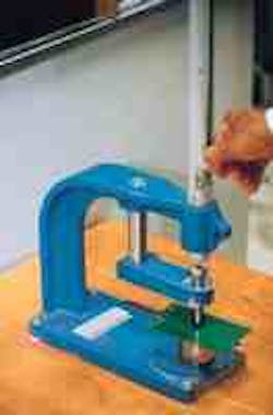
An FBE coated panel is being checked in this impact-test equipment (Fig. 1).
This second of two articles continues an effort to clarify the role of corrosion coatings' mechanical properties in controlling the economics of pipeline construction.
Part 1 of this article (Sept. 9, p. 41) discussed flexibility; the conclusion deals with impact resistance, adhesion, and abrasion resistance.
These properties are distinct from coatings' more important corrosion-protection properties: cathodic disbondment, surface wetting, chemical adhesion, oxygen and water-transmission coefficients, and hot-water absorption.1
A clear understanding of corrosion coatings' mechanical properties will keep their role in project economics in proper perspective.
Long-term effects
Mechanical properties often produce effects clearly observable in the field. These effects often lead field personnel to form strong opinions about mechanical properties' importance and to rank them high among the overall properties.
On the other hand, corrosion-protection properties normally produce effects that are less immediately visible. Quite often, their effects are felt only several years after pipeline installation. Unfortunately, therefore, the more visible mechanical properties are often given more importance than they rightfully deserve.
Moreover, it is mandatory that all coating damages be repaired, inspected, and accepted at the construction site, before the pipeline is completed. Some coating repairs are expensive and time consuming.
In addition, several of the repair materials have long cure times, possibly extending to several weeks. Therefore, it is crucially important to the pipeline construction engineer that he receive the pipe with minimal or no damages.
Since there are many chances for the coating to be damaged during handling, transportation, and installation, it is quite natural that construction engineers demand high impact-resistant coatings in order to minimize those damages.
Although it is understandable, one should remember that changes required to improve one property can adversely affect other properties. It should be noted that, in order to improve one of the mechanical properties, the formulating chemist may have to sacrifice some of the corrosion-protection properties.
Therefore, a good understanding of these mechanical properties and how they relate to the corrosion-protection properties is essential to give each their proper importance and rank them correctly.
A proper understanding of the mechanical properties is also extremely important to those who are involved in pipeline maintenance and concerned with cathodic protection.
Impact resistance
Impact resistance is as important among the mechanical properties as flexibility (Part 1). The value of impact resistance is an indication of a coating's ability to survive damages from impact. The various units used to express impact resistance value are inch pounds, kilogram meters, and Joules.
Accurately measuring this very important property is a troublesome area for both laboratory chemists and field engineers because different factors affect the test results.
Test methods
Because of the joint efforts of several international technical groups, reliable test methods are currently available. ASTM G-14, the falling-weight drop method based on the Gardner Impact Tester, is one of the most widely used methods.2
This tester consists of a ball-ended tup which rests on the evaluation specimen. The test specimens can be either laboratory prepared panels or samples extracted from the pipe.
Fig. 1 shows laboratory impact test equipment for the falling-weight drop method.
A known weight is dropped onto the sample through a guide shaft from a measured distance. The impact energy is obtained by multiplying the height and weight.
The impacted area is then tested for coating damages with "holiday" test equipment. (A "holiday" is any gap in pipeline coating.)
For thin coatings, a wet-sponge holiday detector with 67.5 v is used. For fusion-bonded epoxy coatings, 125 v/mil (2,500 v for 20 mils) hot spark detectors and for thick polyethylene, 25,000 v to 35,000 v (3.5 mm thick coating) hot-spark detectors are the test equipment used to check the samples after the impact.
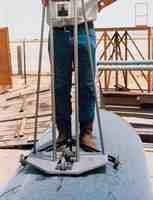
There is impact-test equipment developed by coating applicators to test the impact resistance on plant-coated pipe in the applicator's yard or in the field. One such unit is the Al Qahtani line-traveling impact tester developed by Al Qahtani Pipe Coating Terminal.
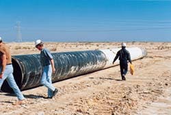
Fig. 2 shows the impact test, with the line-travel impact tester, on a polyethylene coated 48-in. OD pipe at Al Qahtani Pipe Coating Terminal yard, Dammam, Saudi Arabia.
Impact test results can be inconsistent even if the tests are conducted by the same test facility. This is mainly because the factors that influence the test results are often overlooked.
It has to be noted that the tup-end shape, coating thickness, substrate thickness, and substrate temperature all have considerable effect on the impact-resistance test results.
An important but often ignored point is that the impact energy can be absorbed not only by the coating, but also by the substrate and test equipment itself. Since the energy is also absorbed by the substrate of the coated specimen, its thickness and metallurgy can considerably alter the results.
Therefore, to avoid variances, consistency in the test specimen metallurgy and thickness is required.
A joint of 48-in. OD pipe is being impact tested by the line travel impact tester (Fig. 2).
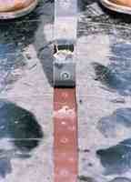
The bottom section of polyethelene coating shows adhesion loss at purposely impacted areas (circles) in a test of the three-layer system (Fig. 3).
Published data
Confusion and misunderstandings still surface among coating professionals regarding the substantial variances in the impact-resistance values published in the coating manufacturer's data sheets and those obtained in the field on coated pipe.
Quite often, this again results from poor understanding of the various factors which affect both the laboratory and field test results. The results published in the coating manufacturer's data sheets are usually obtained through the impact tests conducted at 25° C. (77° F.) on 1/8-in. steel panels on which the substrate can yield upon impact.
As per ASTM G-14, Schedule 40 pipe with the specified coating can also be used for laboratory evaluations. In the case of the tests done on the pipe in the field, however, the substrate is usually thick and does not yield upon impact.
The portion of the impact energy absorbed by the coating is therefore higher and will give a much lower impact-resistance value compared to the thin laboratory test specimen. It is highly possible to have an impact-resistance value of only 4 Joules for the coating on a 0.5-in. W.T. pipe, even though the reported value in the data sheet may be up to 18 Joules.
The effect of coating thickness, substrate thickness, and substrate temperature can be understood by reviewing the impact-resistance values given in the data sheets of various FBE coatings.3
In general, the impact resistance will decrease with a decrease in substrate temperature between 120° F. and -50° F. There are, however, no appreciable changes at greater than 120° F. and at less than -50° F. The impact resistance will decrease when the substrate thickness increases.
The changes are noticeably high for thicknesses between 0.0625 and 0.375 in. The changes are negligible at less than 0.06525 in. and greater than 0.375-in. The effect of coating thickness on impact resistance is different compared to these changes; the values generally increase when the thickness is increased.
This FBE-coated line has been in service since 1984 in the Middle East, operating at 156° F. (Fig. 4).
Two systems
Impact-resistant values vary considerably for various pipe-coating systems. The extent of the variation can be understood by reviewing the impact-resistance values of two of the most popular pipe-coating systems, fusion-bonded epoxy (FBE) and polyethylene (PE) systems.
Coatings having the highest impact resistance are preferred to minimize damages. Corrosion-protection properties, however, are extremely important.
Selecting a high impact-resistant coating to reduce possible construction damages does not make much sense if the corrosion-protection properties of the selected coating system, including the joint coatings, are insufficient to meet the pipeline's design life.
Following this line of reasoning, one could argue that the coating with the best corrosion-protection properties is also useless if it cannot withstand the field construction activities.
Ideally, the coating should have the highest values of both mechanical and corrosion protection properties. Therefore, in the process of coating selection, it is extremely important to review all properties and decide the minimum values for both properties that would allow the pipeline to achieve its design life and lower the construction cost.
The most important point to remember during the coating selection is that the very reason to have the coating in the first place will be lost if the selected coating, even with the highest impact resistance, fails to protect the pipeline from corrosion, at least until the stipulated design life.
It has been proven that thermoset FBE coatings have the best corrosion-protection properties, and the thick thermoplastic systems have the best impact resistance. Therefore, if damages during pipeline construction present the major concern, a thermoplastic coating is the logical choice.
But any coating, including the thermoplastic, can be damaged if the impact force is high enough. The question is, can anyone specify an impact-resistance value which can guarantee a damage-free coating?
This being impossible, the only logical solution is to have a coating with sufficient impact resistance to withstand normal pipeline handling, transportation, and construction activities, so that the corrosion-protection properties need not be compromised.
Industry effort
Considerable effort has been expended by the coating industry to develop a coating with the highest values of both mechanical and corrosion-protection properties but with no success.
The difficulty in combining the best values of both mechanical and corrosion protection properties in a single system has led the industry towards multilayer systems. The three-layer polyethylene and polypropylene two-layer Duval system and Nap-Gard Dual Powder Gold are the multilayer systems developed to achieve this objective.
All these systems attempt to combine the best of both properties. Details of the various components in these multilayer systems are given presently.
The three-layer polyethylene system consists of an epoxy or FBE (5-12 mils; 125-300 m) primer and a polyethylene top coat. In three-layer polypropylene, the topcoat is polypropylene instead of polyethylene and FBE is the bottom layer.
In these three-layer systems, the corrosion-protection epoxy system is connected to the mechanical protection thermoplastic system through a thermoplastic adhesive.
The Duval system consists of only two layers, an FBE base coat and a polypropylene top coat.
The FBE base coat is thick (20 mils, on average) and is bonded to the polypropylene (20 mils, on average). In this system, the corrosion-protection FBE layer is bonded to the mechanical protection polypropylene through a chemically modified component.
All three systems (three-layer PE, three-layer PP, and the Duval) utilize an extrusion process to apply the thermoplastic top coat to the layer underneath. The only system which is different from all of the other multilayer systems is the Nap-Gard Dual Powder Gold System.
This system consists of an FBE (8-12 mils) base coat and 16-20 mils of plasticized FBE top coat. This system utilizes the fusion-bond technology to combine the corrosion protection FBE layer to the plasticized mechanical-protection FBE layer.
The spray application method eliminates the potential air entrapment that is possible with extruded systems. In this system, generically similar curing radicals are used in the crosslinking of the FBE and the plasticized FBE layers.
Because of this, a homogeneous system is achieved with no distinctive layer separation, although it is still considered as a multilayer system.
Although the short-term performance tests for both mechanical and corrosion-protection properties of the multilayer systems are encouraging, some of the professional coating experts have taken a conservative position with the multilayer systems.
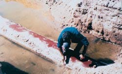
This section of a failed pipeline in the Middle East was coated with polythelene and protected by cathodic protection (Fig. 5).
Caution
Absence of performance history and the concern for the long-term viability of the middle adhesive layer, especially in high-temperature services, have forced them to take this cautious approach.
Another major reason for this hesitation is the absence of suitable field application "friendly" joint coatings (girth-weld coatings). The ones that are proposed are either not homogeneous or are too expensive.
The larger cut-back requirement is also a serious concern which keeps some of the coating experts from fully supporting the three-layer systems.
Even though FBE is considered a thin-layer system, it has good impact resistance and is able to withstand all normal handling and construction activities. Only minor damages are reported worldwide.
If the total consumption of the repair material can be taken as an indication of the coating damages, it appears to be negligible compared to the total volume of the FBE coating consumed.
According to 1982-1994 data available from one of the FBE suppliers, the amount of FBE supplied was sufficient to coat more than 500 million sq ft, while the amount of repair material supplied during that time represents only a fraction of the total area coated with the FBE system.4
The coating damages occurring while in service may translate into increased use of the cathodic-protection current. Discussions with engineers operating FBE lines in the Middle East since 1979 confirmed that only a minor portion of the allotted cathodic-protection current has been consumed, indicating minimum damages during construction and service.
A Direct Voltage Gradient Survey conducted on a recently completed internally and externally FBE coated line in the Middle East5 identified only 17 construction-related holidays in a 123-km pipeline. This is an impressive figure for any type of coating when the severity of several construction activities is considered.
Deceptive appearances
Even though a coating with a high impact resistance is not visibly damaged during an impact, it does not necessarily guarantee that the system is not damaged. This is especially true for some thermoplastic systems for which cohesive strength, an indication of impact resistance, is higher than its adhesive strength.
The system could be damaged and the specified tests not indicate these hidden damages. This was illustrated during the impact test performed according to DIN 30670 on a three-layer PE coated 48-in. pipe.
The pipe was impacted with a 1-kg weight from the specified height at several areas, as specified. The impacted areas were then holiday tested with a 35,000-v hot spark holiday tester. This pipe joint passed the test, indicating no damage to the coating.
An adhesion test conducted at the impacted area, however, indicated poor adhesion. For further investigation, the entire impacted polyethylene coating was peeled off. Fig. 3 shows that the adhesion between the layers was totally lost at the impacted areas.
It should be remembered that this impacted area was tested with 35,000 v, and the electricity did not penetrate the thick PE coating.
If a joint with similar hidden damages is installed, it will have a serious effect on the performance of the cathodic protection system which is designed to protect areas with coating damages. Simply stated, this area will not be protected by the -0.85 v cathodic-protection current.
Experience with FBE under the same conditions is quite different. The adhesive strength of the FBE system exceeds its cohesive strength. Therefore, FBE coating will break before it delaminates if impacted with a considerably large force.
This property lowers the coating's insulative resistance at the impacted area and allows the low-voltage cathodic-protection current to reach the steel surface and protect it. Fig. 4 shows an FBE-coated pipeline operating in the hot, wet Subkha area in the Middle East.
Under certain conditions, a very high impact resistance for the coating may not be the best. The primary role of the coating is corrosion prevention by itself or in conjunction with the cathodic protection system.
For buried pipelines, it is important that the cathodic-protection current be where it is required when it is required. Any obstacle in the electrical path can prevent the current from reaching the pipe surface.
This phenomenon, "cathodic shielding," is a major concern to the pipeline operating engineers.6 Several pipeline failures have been attributed to cathodic shielding on polyethylene tape systems.
A reported failure of the polyethylene tape system is a good example.7 Fig. 5 shows a corroded section of the polyethylene-coated line. This line failed from external corrosion, even though the installation included an impressed-current cathodic protection system.
The protective coating if delaminated from the pipe (during an impact) without any break can actually become the object that blocks the electrical path of the cathodic-protection system.
Ideally, the coating should have enough adhesion to remain at the metal surface after an impact. But, in case the impact energy is high enough to destroy the adhesion between the coating and the metal, then it is preferable to have the coating broken in order to lower its electrical (insulative) resistance at the impact site for the low cathodic-protection voltage to pass onto the metal surface.
It is important to realize, therefore, that to be an effective part of the cathodic-protection system, the coating's adhesive property must be higher than its cohesive strength. Although a very high impact resistance is desirable, it should not exceed the adhesive strength, because impact damages are unavoidable.
One may have to agree8 that under certain conditions, therefore, a coating with the highest impact energy is not always the best choice. Other properties also have to be considered before the final choice is made.
Adhesion
The adhesion property of the coating plays an important role because it controls the coating's delamination characteristics.
It is obviously important that the coating remain adhered to the pipe during the mechanically intensive plant application and field construction activities.
Adhesion also plays a key role in the corrosion-prevention capabilities of the coating. This property becomes one of the key properties because it influences both mechanical and corrosion-prevention properties.
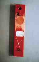
Here is a sample of FBE coating after adhesion tests (Fig. 6).
Pulling force
Adhesive strength is the force required to pull the coating from the substrate without fracturing it. A coating's adhesive strength is the total sum of several components, the major ones being mechanical, polar-polar, and chemical adhesions.9
Although only mechanical adhesion can be considered a true part of the mechanical properties, a thorough understanding of polar-polar and chemical adhesions is helpful.
By definition, mechanical adhesion is the gripping force of the coating onto the metal surface. Polar-polar adhesion is the force of attraction between the positive and negative poles of the chemical radicals (hydrogen bonding) in the metal surface and the coating.
Chemical adhesion results from the chemical bonds that are established between the reactive sites of the substrate and the coating through chemical reactions. Although mechanical, polar-polar, and chemical adhesions all play significant roles in the total adhesive strength of the coating, the strengths of each of them are quite different.
It has been claimed that mechanical adhesion is the weakest of the three. It is also claimed that a chemical bond is 20-1,000 times stronger than a polar-polar bond.10 Therefore, the coatings which establish the greatest number of chemical bonds will have the highest adhesive strength.
It has been found that FBE coatings have higher adhesive strength than polyethylene systems. This is mainly the result of chemical bonds established by the FBE. Polyethylene does not form chemical bonds with the substrate.
ASTM D4541 is the standard method for determining the adhesive strength of several types of coatings. In this method, the coated specimen is glued to a dolly which is pulled by an elcanometer after allowing sufficient time for the glue to dry.
The force required to pull the coating from the substrate is recorded as the adhesive strength.11
Although ASTM D4541 is the widely used method, it has limitations which can seriously affect results. One limitation is that the value which can be obtained will always be equal to or lower than that of the glue.
For example, if the adhesion value of the coating is 8,000 psi and of the glue is only 5,000 psi, the maximum adhesion value which can be obtained through this method will be 5,000 psi at which the glue detaches from the coating.
Another limitation is that this method will not give the true adhesion value if the coating fractures. In both cases, one can and should report the value and state the situation as glue detached or coating had torn.
Fig. 6 shows an adhesion-tested FBE sample. Section A shows the area where the dolly was glued. When failure results from rupture of the glue, the reported value indicates only the adhesive strength of the glue to the coating. In such cases, one can only state the adhesive strength of the coating is greater than this value.
Another widely used adhesion test method is the X-cut method. An X cut is made on the coating which goes all the way to the metal substrate. With a sharp knife, the coating is removed starting from the intersection of the X cut.
The distance that the coating is removed completely, with no coating left on the substrate, is measured from the intersection of the X cut to determine the pass or fail result.
This is a very subjective test in which great discrepancies in the test result can be reported. Section B of Fig. 6 shows an adhesion tested area of the FBE sample using the X cut method.
Abrasion resistance
ASTM D4060 is the coating industry's standard test method for abrasion resistance.12 Even though this property is important for internal coating used for controlling erosion corrosion, it is less important for external coating.
The only advantage for an external coating with excellent abrasion resistance is that it can prevent minor damages during the transportation and construction activities. Therefore, less importance is given to this property compared with other mechanical properties.
References
1. Varughese, K., and Jacob, S.P., "Critical properties of protective coatings which affect corrosion prevention of underground pipeline," Seventh Middle East Corrosion Conference, Bahrain, February 1996.
2. ASTM: G-14-88: Impact Resistance of Pipeline Coatings (Falling Weight Test): Annual Book of ASTM Standards, 1991. Vol. 6, pp. 1040-1044.
3. Product Data Sheet, 3M 206N, October 1983, 3M, Electro products Division, Minneapolis.
4. Bethea, John D., unpublished data collected 1982-1995 for Nap-Gard Products, O'Brien Corp., Houston, 1996.
5. Unpublished data collected during the direct-voltage gradient survey (DVGS) on one of the internally and externally FBE-coated pipeline in the Middle East, 1995.
6. Varughese, K., "Factors Influencing the success of In-Situ Rehabilitation of High Temperature Pipeline," 10th International Conference on Pipe Protection, Amsterdam, November 1993; group publication No. 7, Mechanical Engineering Publication Ltd., London.
7. Ward, D.K., Moore, E.M., Hawkins, P.J., "External and Internal Pipeline Coatings in Arabian Gulf Area," 5th International Conference on the Internal and External Protection of Pipes, Innsbruck, October 1983.
8. Mills, G.D., "The Role of pipeline coatings in Mitigating Corrosion," International Conference in organic Coating Science and Technology, Athens, July 1986.
9. Packham, D.E., "Adhesion Aspects of Polymeric Coatings," K.L. Mital, Editor, New York, Penum Press, 1983.
10. Mills, G.D., "A Proposal of the Theoretical Mechanisms of Foam Formation, Adhesion and Cathodic Disbonding of Fusion Bonded Epoxy Coatings," Corrosion '86, Paper No. 313.
11. ASTM: D 4541 Fixed Alignment Adhesion Testers-Elcanometer Model 106 Adhesion Tester, Annual Book of ASTM Standards, 1991, Vol. 6, pp. 835-836.
12. ASTM: D 4060: Standards Test Method for Abrasion Resistance of Organic Coatings by Taber Abraser, Annual Book of ASTM Standards, 1991, Vol. 6, pp. 676-678.
Copyright 1996 Oil & Gas Journal. All Rights Reserved.
