TECHNOLOGY Vessel movement influences offshore communications system design

Stanley R. Holcomb
Brown & Root Inc.
HoustonStephen D. Burger
Amoco Orient Production Co.
Chiwan, China
Communication links for the Liuhua 11-1 oil production project, offshore China, required a system that would function with vessel movement under typhoon conditions of heavy rainfall and extreme wave action.
The system includes a microwave path between two floating production facilities and a satellite connection between the offshore facilities and onshore China (Fig. 1 [21206 bytes]). The system provides multiple local-area-network (LAN) linkages, and voice with fax in English and Chinese.
The satellite link has a geostabilized platform offshore and a China National Offshore Oil Corp. (Cnooc) master earth station onshore. System operations started in mid-1995.
The second system, with an omnidirectional micro- wave link between vessels, began operating this spring.
The Liuhua development partnership consists of Cnooc, Amoco Orient Petroleum Co. (AOPC), and Kerr-McGee China Petroleum Ltd. AOPC is operator.
Also, the project included many contractors and subcontractors such as Brown & Root Inc. and Alaska Telecomm Inc., the principal contractors for the communications links.
Project specifics
Liuhua 11-1 is about 120 miles southeast of Hong Kong. Onshore operations offices are in Chiwan, in the Shekou area, Shenzhen province, just inland of Hong Kong.
Facilities at Liuhua 11-1 include two converted oceangoing vessels which are moored within 1.7 miles of each other (Fig. 2 [20370 bytes]).
A converted semisubmersible drilling rig serves for both drilling as well as a surface control base for the extensive subsea production equipment. It is designed as an FPS (floating production system). It is permanently moored and semisubmersed, and it experiences only slight movement from wave action.
The other facility, a converted tanker, is designed as an FPSO, or floating production, storage, and offloading facility Fig. 3 .
The FPSO is moored with a large swivel turret near the bow of the vessel. Massive anchors are positioned in a large circle on the seabed and fastened to the swivel on the FPSO.
The FPSO will weathervane, or swing on its mooring with wind and tide action, and will experience considerable pitch, roll, and heave movement from wave action.
Vessel movement is a challenge for the communications system. During storm conditions, reliable, high-speed data and voice communications are essential for planning and conducting systems shutdown and vessel evacuation. In designing these communications links, we found that the choices were limited for systems that could be depended on when communications are most important.
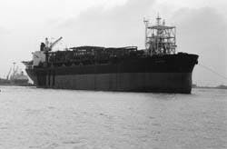
Facilities in the Liuhua 11-1 oil field include a converted tanker for production, storage, and offloading (Fig. 3).
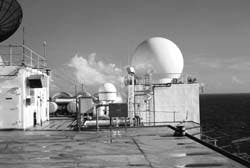
A radome houses the Ku-band antenna for the satellite system (Fig. 4).
Communications needs
The two offshore vessels have drilling and production staffs, as well as cooks, ship captains, and maintenance technicians. The vessels have complementary operations agendas that require, in some cases, rapid and reliable data exchange of critical process equipment status and production rates.
The emergency shutdown systems on each vessel communicate operational status and alarms with the other vessel. Engineering offices have personal computers (PCs) that network with other PCs on both vessels and to onshore offices.
The principal data exchange is for logistics. The warehouse people are already asking for more speed and PC network capacity.
Although there is telephone voice and fax traffic between vessels, most communications is with the onshore support staff.
Hand-held radios are used for crane operations, helicopters, supply boats, shuttle tanker loading, and many other daily tasks. Also, the maintenance and offloading workers need these radios below decks.
There are no plans for an offshore maintenance staff for communications equipment. Further, very little support is anticipated for the onshore portion of this equipment. For this reason, the communications equipment includes maintenance diagnostics and is interconnected for control using small network management protocol (SNMP) interfaces and features where available. An on-call maintenance contract is anticipated for communications systems repair calls.
The initial operations staff will be from AOPC and Cnooc.
Amoco international communications methods and systems are being interfaced. The telephone systems are compatible to Amoco's Socon international dialing scheme. Also, for consistency and compatibility, the project uses Amoco standard routers, bridges, and multiplexers. Ethernet addresses were coordinated and assigned by Amoco in Chicago.
Onshore to offshore
A division of Cnoop, the Nan Hai East division (Conhe), operates and maintains a master earth station in Shekou. Thus, it was relatively simple to select the appropriate satellite carrier and station.
After verifying that this station was applicable, the design then focused on the offshore implementation to best utilize this resource.
Because the Liuhua area is prone to monsoon rains and typhoons, the offshore facilities will have to be evacuated during typhoons, and these evacuations and related shutdown activities must be coordinated with the onshore staff.
When the need for the link is most critical, heavy rainfall and extreme wave action conditions will prevail. The communications equipment has to be reliable under these typhoon conditions.
C-band
Conhe operates a C-band master station in Chiwan. The satellite is the Asiasat-1 operated by Asia Satellite Telecommunications Co. Ltd. of Hong Kong.
Based on experience with other projects, this was and continues to be a reliable station and staff for both master station and satellite. The data for this satellite show that both onshore and offshore sites will be in the north beam, second contour.1 This should provide good 34 dbw (decibel watts) signal power.
In this project, the C-band is preferable to the Ku-band, although there are many successfully Ku links in these conditions on fixed stations. The C-band is lower frequency and thus less attenuation due to rain is allowed.2
Note that for a C-band the down-link attenuation, A, is calculated as:
A = 0.0008R1.17
R is rainfall rate in mm/hr and A is in db/km. For the Ku-band this calculation is as follows:
A = 0.0025RL1.18
Obviously, much higher attenuation would occur in heavy rains with a Ku station.
Moving platform
The FPS is expected to move less than the FPSO. Sofec Inc. predicted the movement in a 100-year monsoon as:
- FPS-Roll +-4o, pitch +-3o, yaw +-2o
- FPSO-Roll +-7.37o, pitch +-5.67o, yaw +-2.9o.
Most processes will be controlled from the FPSO, but obviously the FPS will have the least movement, and was selected as the best platform for the offshore satellite station.
Amoco had successfully used a geostabilized platform supporting a Ku-band antenna on a short term, offshore drilling project. Because this equipment became surplus, it was logical to investigate refurbishing it for Liuhua.
This "Startrack" (Techwest of Burnaby, B.C., a suburb of Vancouver) system could be modified economically to mount a C-band antenna.
An Andrew 3.6-m antenna was selected to enhance reliability during monsoon conditions and improve the "link budget." A radome (Fig. 4) protects the antenna dish from wind loading and prevents water fill because of the severe up angle that was required because of the almost overhead satellite.
A geostabilized platform has some interesting aspects. For one, in the link budget calculations, one may use zero pointing error. The stabilized platform homes on the satellite beacon, and constantly "nutates" (wobbles) around the signal to keep optimum signal strength. Thus, it does not matter how well the satellite crew keeps its "bird" on station. For this reason, one major market for stabilized platforms is for otherwise useless, unstable satellites.
On the other hand, the system is active, not passive pointing, and therefore must be operating correctly to receive a signal. The benefit to the satellite operator is that the offshore station cannot interfere with another satellite because it cannot point at it unless it has the same beacon.
Because of controversy about too many satellites in this same area, side lobes were of great concern. Asia Satellite required the running of a complete set of pattern tests on the antenna with the platform operating and fixed.
Another interesting engineering aspect of stabilized antenna platforms is that they are dynamic, and can be dynamically unstable. Because the system was modified with a much larger, heavier antenna than the original, Techwest used its motion simulator to run extensive tests.
The heavier weight changed the dynamics, and the system oscillated badly. It was necessary to add more framework stiffening to smooth out the operation. The original antenna mounting frame was too flexible for the larger torque motors and heavier, larger antenna. The stiffening did the trick, and the system works well.
It is quite impressive to see the floor rocking and rolling like a ship in a storm, and the big 3.6-m antenna solid as a rock on the signal.
DAMA
Asiasat-1 is a Hughes telephony earth system (TES) satellite. It was designed to handle telephone calls, one per channel, and uses a technique called DAMA (demand-assigned multiple access) which assumes that a channel will be used for a single-voice conversation and then go idle until the next caller.
The system can be tricked into staying on line to provide a continuous channel by using a channel unit (CU) to lock in a single channel. It will then behave like an SCPC (single-carrier per channel) system, a method used by the Conhe earth station.
The standard channel width is 64 kb. If later this is found to be too restrictive, the operations team would need to apply for a second channel.
With two channels, the original channel would remain as is, and the second channel would be a higher speed data channel because data flow is expected to be the principal bottleneck.
Multiplexer
Because at both ends of the satellite link the signal is split into voice and data channels, an access multiplexer at each end provides network and PABX interface.
Amoco's standard multiplexer was selected. The system provides four voice channels and one data channel output. The voice channels are condensed to 9.6 kbps (kilobytes/sec) by the CELP algorithm. The data channel is 19.2 kbps.
These units allow dynamic allocation, but it is not being used at this time. Fax compatibility is provided. During factory acceptance testing, the quality of Chinese (Mandarin) voice communication over this CELP link was found to be good.
PABX interface
The hope was that all three stations could be tied together with compatible PABXs, such that the telephone system would share control features, and "look like" one system. But this could not be done for the two offshore sites. At the time, the PABXs needed T1, (or E1) linkage to affect a control interface.
The multiplexers for 64 kbps could not provide the fractional T1 linkage over the satellite link. Thus, multiplexers carry four voice trunks between the onshore and offshore PABXs. Because of this, the PABXs were not compatible, and indeed they are different brands and styles.
Another early difficulty was that direct inward dialing (DID) lines could not be obtained for the onshore office PABX. Therefore, it is set up as an attendant system. Work continues on finding ways to make an attendant system allow inward dialing. Alaska Telecomm has had some success in this.
LANs
The project has three different types of local area networks (LANs) offshore, and one onshore. The onshore and one of the offshore LANs are Novell.
The Novell LAN is implemented as IEEE Std. 802.3, 10baseT, which is DOS based and uses a twisted-shielded-pair cable and RJ-45 connectors.
The other two offshore LANs are GE-Fanuc's implementation of TCP/IP ethernet and Modicon's Modbus Plus.
The TCP/IP is UNIX based and uses thin wire coax cable. The Modbus Plus networks use a twisted-shielded-pair cable. Both Modbus Plus and TCP/IP use BNC connectors. Thus, there is a significant variation in speed, protocol, file structure, and hardware interface for the LANs which this project supports.
The offshore LANs are interfaced between vessels, and the onshore and offshore Novell LANs are connected. Thus, routers are at both ends. The offshore router connects the TCP/IP LAN as well as the 10baseT LAN.
One offshore vessel's Novell traffic is routed through the other vessel's router before being connected to the onshore LAN. If a GE-Fanuc control station were set-up onshore, it could interface the TCP/IP networks and provide remote control of both vessels, but this feature is not being implemented.
In fact, the offshore router is setup to block incoming TCP/IP traffic. The main reason for the connection is to provide for downloading control systems' archive records such as production rates, usages, etc. Note, that one interesting twist is that the UNIX control system files are downloaded into the Novell DOS file structure.
Amoco's standard routers are used, again principally for compatibility.
Copper path
Because the distance from the project office building to the master earth station in Chiwan is less than 1 mile, this link is provided by a copper path and limited distance modems (LDMs).
Spread-spectrum radio link was considered for this, but the local authorities seemed more comfortable with the hardwired link. Three other projects in Chiwan use the master earth station and hardwired links to their office complexes.
Vessel to vessel
The communications link between the two converted vessels is by microwave radio.
Although this project was scheduled to use microwave radio from the earliest preliminary engineering, several other alternatives were investigated.
The reasons for not want ing microwave was that the vessels are close together, with a flat over-water path and a good possibility that the flare on the FPSO will be directly in the signal path as the vessel rotates.
Amoco would have preferred a fiber or copper conductor signal paths. However, because the produced crude goes through two flexible risers and a complex rotary joint from the subsea manifold onto the process deck of the FPSO, there was no dependable way to install a slip ring or joint through the mass of crude oil piping and rotating joints. Although fiberoptic rotary joints were available, they were unproven for this application.
The LAN links needed high reliability at high data rates and 2-ghz systems had good results in past projects. Therefore, this was chosen as the principal link between vessels.
Too close
The vessels are well within the usual 3-mile minimum for microwave path calculations. The Harris-Farinon program was quick to give a warning in this regard. Fresnel interference is not only possible, it is likely.
Fresnel interference occurs when a reflected signal path length is such that it is received in opposite phase to the direct path. Also, as the vessels heave and pitch, the interference will fade in and out with the wave motion.
Because the FPSO's draft will vary as the oil is loaded and offloaded, the height of the antennae will vary accordingly. Thus, one cannot use the usual ploy of choosing and adjusting an antenna height for least interference.
A spreadsheet was developed to plot the interference potential with the vessel movement and resulting path length variations (Fig 5 [20972 bytes]).
The path in this case is such that one can clearly "see" the direct path and the midpoint reflection point from either end. The reflection point is the ocean surface (Fig. 6 [18436 bytes]).
The vessels are too close together to assume that the reflected signal will be a weak scattered signal. If we visualize a calm flat sea surface, the prospect of total loss of signal seems possible.
Antennae placement
Each vessel's central area does not have room for communications antennae be- cause on the FPS this area is occupied by drilling equipment and on the FPSO by process equipment. Also, the possibility of stormy seas prevents antenna placement near the water line on either vessel. A low placement on one end would otherwise avoid the midpoint view.
Equipment location on the FPSO is another problem which effects antenna placement. The bow of the FPSO is moored, and the vessel swings with the weather. Thus, large waves will occasionally break over the bow.
Therefore, no space is available on the forward part of the vessel for radio equipment. It must be located aft, in the raised accommodations section.
Unfortunately, this part of the FPSO sweeps a large arc as the vessel weathervanes. Distance between antennae varies by at least the 300-m diameter of this arc. This swing also means that an omnidirectional antenna must be installed on the FPSO.
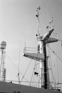
The mast of the FPSO provides a high place for the omnidirectional 2-ghz antenna (Fig. 7).
Omnidirectional antenna
An omnidirectional antenna is not really all directional. It has more of a flattened doughnut pattern that could be a serious problem.
As the FPSO pitches and rolls, the doughnut tilts. It is conceivable that the vessel would pitch enough to totally miss the FPS with its signal, pointing off into the sky on one extreme and into the water on the other. Thus, the omnidirectional antennae cannot be very directional, or efficient.
The FPS antenna could be a parabolic design, but again it cannot be very directional or the FPSO swing will take the receiving antenna out of the FPS pattern.
The principal result is that the antenna system cannot be very efficient, and the high gain expected by the short distance is sacrificed to compensate for the directionality problems.
Gas flare
Many old-timers in the oil patch have stories of flares totally interfering with microwave radio signals. Published opinion believes this cannot occur. However, on the FPSO, the flare is forward of the swivel, and will sometimes be directly in the microwave path.
This is a concern because if there is an occasional massive blowdown, the radio system must operate properly to transmit emergency shutdown signals.
Expert opinions
Two opinions from published experts on the subject of microwave transmission over open water gave two, almost opposite opinions.
One was very concerned and recommended a multiple radio system and frequencies split with a recombined signal at the baseband on either end. The other expert felt that a sufficient signal could be obtained with a standard 2-ghz system to overpower any potential interference or directionality fading problems.
Most people in Amoco's international communications group held the latter opinion.
The local authorities preferred the 2-ghz band with minimal frequencies used and authorized. Thus, multiple frequency diversion did not seem to be available.
The solution that was adapted used as much of everybody's opinions as possible with the objective of obtaining a stable, reliable link.
A standard redundancy, 2-ghz microwave system was installed. Also a 450-mhz radio system provides an alternate signal path and antenna location scheme.
2-ghz radios
A 2-ghz, receive redundancy, microwave radio system was as standard a system as could be obtained. These systems have provided good results and are supported at Liuhua by the manufacturer.
The receive redundancy is relatively easy to implement and is also a widely accepted and proven design. In this design, the radios transmit on a preselected antenna, but will automatically switch receive antennae to get the best signal. There are also hot standby transmitters and receivers. The system has more than enough bandwidth for this project.
The system fault and failure alarms from these radios are attached to the vessel's facility control system for operations staff notification of 2-ghz system problems.
The PABXs on each vessel are connected via T1 cards in the PABXs and in the 2-ghz systems' channel banks.
Two additional data lines are provided for LAN linkage between vessels. One LAN link is to connect Novell networks on the respective vessels, and then route them through to the onshore Novell LAN.
The other data circuit is actually two Modbus links, one in each direction for the emergency shutdown systems (ESD) linkage. At this time, this linkage is for operator alarm only, but it could be reprogrammed to trip once the operations staff gains confidence in the reliability of this communications link.
Both of these LAN links are repeated in the back-up 450-mhz system. A special ring-down circuit provides direct hot-line communications between the control room operators on the respective vessels.
2-ghz antennae
On both vessels, the 2-ghz antennae are placed close to the respective communications equipment rooms. This is because of concerns about the low-gain antennae and the additional loss that long antenna leads would cause.
The antennae were placed on the FPSO as high as possible (Fig. 7), and the antennae on the FPS as low as possible to minimize the midpoint reflection view and to clear the process equipment on the FPSO deck.
The flare position was not considered for positioning the 2-ghz antennae. On both vessels, there are two antennae separated vertically. The FPS antennae are parabolic directional, and the FPSO antennae are omnidirectional.
450-mhz radios
Nonredundant 450-mhz radios were installed as back-up to the 2-ghz system. These provide frequency diversity and are in a frequency less likely to experience fresnel interference.
The radios cannot carry the full load that the 2-ghz system carries; therefore, only the LAN connections are carried as redundant links.
To provide emergency voice lines if the 2-ghz system is down, the PABX routes four telephone lines through the 450 system. The Novell LANs are linked, also through the routers, but at a lower speed than on the 2-ghz system. The Modbus links are exactly duplicated.
The control systems are programmed to use the 450 system Modbus linkage alternately with the 2-ghz system.
When attempting to use the 450-mhz system, it will then alarm and switch over to the 2-ghz link if the 450-mhz link is lost and cannot be regained. This provides the operations staff with a means to monitor the operation of the 450-mhz system. The 2-ghz faults and alarms are wired into the facility control system.
450-mhz antennae
The 450-mhz antenna on the FPS was placed close to the communications equipment room. The FPSO antenna, however, was intended to provide some space diversity. There was insufficient space to provide the distance required as recommended:3
S = 3lR/L
S is the separation distance, l is wavelength, R is the effective earth radius, and L is the primary signal path. All distances are in kilometers.
The antenna was placed as far forward as possible, on the swivel turret structure. The disadvantage is that this requires a very long antenna cable, about 230 m. But the losses appear to be acceptable using 7/8-in. Heliax cable.
Another advantage of this location is that because the antenna is on the swivel structure, the view from the FPS changes very little as the FPSO weathervanes.
Link implementation
The telecommunication contractor for this project was Alaska Telecom Inc. (ATI). Amoco's master earth station in Tulsa was very supportive and played a major role in implementing the satellite communications portion of this project.
Full system setup
After the stabilized platform was refurbished in Canada with the new antenna and radios, it was torn down, repackaged, and shipped to Houston for full system staging and testing. The radome had already been shipped to Singapore where the FPS was being refurbished.
To prove linkage into Amoco's communication network, Amoco rented space on a satellite and setup a link from Houston to Amoco's master earth station in Tulsa.
The plan had Amoco in Chicago download the routers with the proper addressing and routing instructions. This was initially unsuccessful in that the router had been programmed to think it was offshore China, talking through Asiasat to the Nan Hai East station. But after giving it a dummy address, the link worked well.
It was also thought that the system would fail over to the redundant router simply by turning the active unit off and having the system look up another route through the standby router. Initially, this did not work because of a lack of patience.
The system would wait 15 min before looking for another route. Once the problem was identified, it was found that the link could be reprogrammed to look for another route sooner.
Antenna pattern
Asia Satellite was firm in requiring a complete antenna pattern test. Because the system would be installed on a floating platform, this test had to be done from Houston.
After a fine pointing mechanism was purchased and installed, Andrew Corp. successfully tested the antenna. The system was then left on overnight in a fixed position to note the stability.
A slight drift was noted in the transmitter. It stayed in specification limits, but was definitely showing a long period saw-tooth frequency drift. At the time it was decided to leave it alone, which turned out to be a bad decision.
Safety, control system
Because the same Amoco/ Brown & Root design team was responsible for both the safety and control system and the communications system, the implementation of both systems was coordinated together.
The microwave linkage and routers were setup in the control systems shop for coordinated testing. Cable and attenuators simulated the radio path. Both the Modbus and the ethernet links successfully operated together. The link redundancy was thoroughly and successfully tested.
The only problem experienced was in determining a method for moving data files from the UNIX-based operator interface station (OIS) system to the DOS-based administrative LAN system.
This was eventually accomplished with a GE-Fanuc programmer creating a script for periodic download to a DOS directory in the OIS server. In this manner, the administration people at the onshore base can simply access the periodically downloaded production data files from their Novell 10baseT stations.
Setup in Chiwan
After the routers and multiplexers were moved to the Nan Hai East master earth station in Chiwan, a looped linkage through Asiasat from, and back to, the Nan Hai station was established using the spare FPS router and permanently installed onshore equipment.
The copper path to the project offices was also tested. This was successful after a brief delay to obtain the same program versions in the multiplexers.
Offshore start-up
The system was started as soon as the FPS was towed to the offshore site. It came up immediately, although there were some drifting synchronization problems, which eventually were traced back to the drifting transmitter.
It was replaced, and eventually replaced again before the transmitter drift problems were resolved.
After operating for over a year, the only real problems have been with the two transmitter failures. The people using the system complain about the speed of the data link, but that can be resolved by leasing another 64 kb channel, just for data.
Implementation
Recently, the FPSO vessel was positioned and the microwave systems powered up. The initial results are consistent with the engineering expectations. The microwave system operates, but with some reflection problems.
The antennae on the FPS end were repositioned to a lower position to reduce the reflections.
References
1. The World Satellite Almanac, p. 722.
2. Telecommunication Transmission Handbook, Roger Freeman, John Wiley & Sons, Third Edition.
3. Telecommunications Transmission Handbook.
The Authors

Stanley R. Holcomb was the lead communications and control systems design engineer for the Liuhua 11-1 project. He has been with Brown & Root Inc. in Houston since 1968, working mostly on offshore energy projects.Holcomb has a BS in physics from Auburn University. He is a registered professional engineer.

![Fig. 1 [21206 bytes]](http://images.pennwellnet.com/ogj/images/ogj/622ho-1.jpg)
![Fig. 2 [20370 bytes]](http://images.pennwellnet.com/ogj/images/ogj/622ho-2.jpg)
![Fig 5 [20972 bytes]).](http://images.pennwellnet.com/ogj/images/ogj/622ho-5.jpg)
![Fig. 6 [18436 bytes]](http://images.pennwellnet.com/ogj/images/ogj/622ho-6.jpg)
Stephen D. Burger is currently the commissioning manager for Amoco Orient Petroleum's Liuhua 11-1 project in Chiwan, China. He has worked for Amoco for 7 years in the worldwide engineering and construction group. Burger has a BS in electrical engineering from the University of Tulsa. He is a registered professional engineer in Texas.
Copyright 1996 Oil & Gas Journal. All Rights Reserved.