TECHNOLOGY Threaded riser connectors save time in deepwater installation
Steve Brashier
Enserch Exploration Inc. HoustonJoseph R. Roche
Hydril Co. Houston
Installation of threaded connectors on the 12-in. oil and the 8-in. gas export risers on Enserch Exploration Inc.'s Gulf of Mexico, Garden Banks (GB 388) production system saved both installation time and costs.
Original plans for the GB 388 floating production facility (FPS) called for welding the joints to assemble each riser. However, during the planning stages, an evaluation showed that threaded connectors (Fig. 1 [64365 bytes]) instead of welding im proved project economics.
Moreover, if it became necessary to pull and re-run a riser (which actually happened), the clean fast make/break of the threaded connection (Hydril Co.'s Series 2000) further reduced time and costs.
Riser system
In mid-September 1995, Enserch completed installation of all major components and initiated production from two previously completed satellite wells at its GB 388 development. The GB 388 development is about 207 miles southwest of New Orleans and includes a converted semisubmersible floating production facility (Table 1 [16373 bytes]).
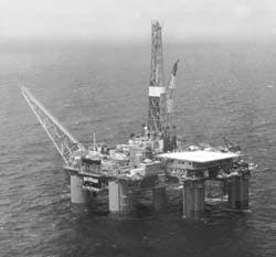
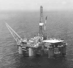
A converted semisubmersible serves as the floating production facility for Enserch Exploration Inc.'s Garden Banks 388 development in 2,096 ft of water (Fig. 2).
The FPF is permanently moored over a 24-slot subsea template in 2,096-ft of water and is capable of simultaneous drilling and production. Oil and gas are produced through individual template flow lines to the freestanding production riser system that is attached to the template at the riser base.
The production riser contains 48 individual strings of production and annulus tubing that convey the produced fluids to the top of the riser, then through flexible flow lines to the FPF. Primary separation and processing equipment onboard the FPF is capable of hand ling 40,000 b/d and 120 MMcfd of gas.
Separate oil and gas streams are transported back down through flexible export lines to 12 and 8-in. OD export risers installed through the production riser. Two, 12-in., 54-mile gathering lines transport the oil and gas to a four-leg jacket shallow water facility in Eugene Island Block 315, installed in 250-ft of water (Fig. 3 [128554 bytes]).
After final processing and dewatering the production is exported to a sales tie-in point near the Eugene Island platform.1
The freestanding production riser system was previously installed on Enserch/Placid's Green Canyon 29 project (GC 29). The riser system components were completely refurbished and 11 new joints were built to extend the water depth capability from the 1,520 ft at GC 29 to 2,100 ft at GB 388.
The production riser is connected to the 24 well subsea template at the riser base using an hydraulically actuated collet connector. Located above the lower riser connector is a titanium stress joint that provides the flexibility needed to prevent abrupt bends in the riser at the riser base and prevent buckling of the freestanding production, annulus, and export lines.2
Above the stress joint are 36, 50-ft rigid riser joints and one 34-ft pup joint. The top of the riser is at a water depth of 180-ft. Each riser joint, about 8 ft in diameter, contains syntactic foam buoyancy modules to offset each joint's 62,000 lb air weight. The weight of each joint in water is 2,000 lb. Internal air cans offset the weight of the production and annulus tubing and export riser.
At the top of the riser, five external air tanks, 15 ft in diameter and 23 ft long, provide additional buoyancy that allows the riser to remain freestanding in severe weather and current conditions.
The upper riser connector package at the top of the riser allows the interface to connect flexible production and annulus flow lines and flexible export lines between the FPF and the riser. To prevent damage to the flexible flow line and export lines, also attached to the upper riser connector package is a tether system composed of six, 40,000 psi tensioners and lines that restrict the riser top's movements relative to the FPF.2
Riser installation
The initial steps for installing the production riser from the FPF entailed running the stress joint, 36 riser joints, and external air tanks. The next step in the installation called for running the 12-in. OD oil export riser through the 20-in. landing string and into the 15-in. ID central guide tube of the riser joints. Later, the 8-in. OD gas export riser was run in the 10-in. ID guide tube located within the external array of production and annulus guide tubes that are in the syntactic foam modules around each riser joint.
The original plan for installing the 12 and 8-in. export risers was to follow the same procedures used by Enserch/Placid in the Green Canyon 29 system, which was seamless line pipe with welded connections. The welds were to be X-rayed for defects on the rig floor as the risers were being run.
It became apparent that the welding and non-destructive evaluation (NDE) process could become a very time consuming and expensive process. Tangible benefits could be realized with threaded connection.
Advantages of threaded over welded connections were identified as:
- Saved time because a welded connection would require 3-4 hr for handling, welding, NDE inspection, and shrink sleeve application. The export riser installation is sensitive to weather because of the inability to stop in the event of severe weather.
- Allowed quick and efficient retrieval of the export riser with threaded connections if it became necessary because of a tie-back tool failure or failure to obtain pressure tests. This would eliminate pulling and rebeveling and rewelding after equipment repair.
- Eliminated safety concerns associated with personnel exposure to numerous X-ray NDE on welded connections. Threaded connections require conventional running and handling procedures that are familiar to rig personnel.
- Eliminated the potential for slag and weld debris dropping down the export riser with threaded connections. Weld debris could hinder the proper function of tie-back tools and seals.
The GC 29 riser installation was in 1,520 ft of water. The time required associated with running and welding the export riser connections took 78 hr for the 12 in., and 42.5 hr for the 8-in. export risers. One weld repair was required on the 12 in. and two repairs on the 8 in.
A simple analysis of the welded connection cycle time experienced on GC 29 showed that the average connection time at GC 29 was 3.39 hr and 1.7 hr for the 12 and 8-in. export risers, respectively.
Using these same averages, it was calculated that for GB 388 a connection time of 159 and 80 hr would be required for the 12 and 8-in., respectively. This was based on 47 connections for each of the export risers.
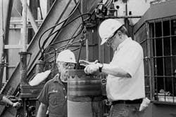
A seal ring is being installed in the treaded riser connector (Fig. 4).
This large block of time was identified as a key area for improving the riser installation schedule as well as an area of concern for weather contingency planning. A search for a threaded connection to improve the time and associated cost for the export riser installation led to the consideration of Hydril's connectors (Fig. 1 [64365 bytes]).
Hydril's designs had to be reviewed for acceptability by both Enserch's contracted engineering analyst and American Bureau of Shipping certifying authorities on behalf of the U.S. Minerals Management Service.
Full-scale prototypes of both sizes of connectors were built and tested. Integrity tests verified design objectives.
It was assumed that the connection cycle time (which includes pickup, stab, make up, shrink sleeve installation, and lowering the joint) for the threaded connections would be about 1 hr for both the 8 in. and 12 in. The total connection time of 94 hr would save 145 hr in riser running time.
With an estimated daily rig cost of $45,000/day, potential rig time savings would amount to $271,875. Offsetting the rig-time savings was the threading connections cost of $166,850. Net savings were estimated to be $105,025.
Enserch's target date for installing the export risers mandated an aggressive schedule for inspecting the pipe, machining the male threads, manufacturing the couplings and seal rings, casting-on sacrificial anodes, applying protective coating, and transporting the finished pipe joints to the shore base for service vessel delivery to the rig.
Machining the threads, seal seat, and torsional locking lugs directly onto the pipe wall saves money that would be otherwise spent on welding and X-ray inspection performed aboard the rig or on weld-on of connector ends at the factory.
Experience at GB 388
The connection time during the export riser installation proved to be better than estimated. Average connection time was 34 min/connection for the 12 in. and 27 min. for the 8 in. One 12-in. thread was damaged during make up and was cut off, welded and X-rayed. If the additional time required for this extra welded connection is included, the average connection time for the 12-in. increased to 40 min/connection.
Fig. 4 shows the installation of the seal ring in a connector.
It is important to note that, if this had been a pipeline installation, automated procedures would have shortened joint cycle time considerably.3
Considering only the connection time required to run the export risers, the total net savings at GB 388 was $182,875 (Tables 1 [16373 bytes] and 2 [10821 bytes]).
An extra benefit of the threaded connection was realized when the 8-in. export riser had to be retrieved. After 43 joints had been run, the riser became stuck in the fiber glass guide tube in one of the lower production riser joints. This was due to an out-of-round guide tube that had not been detected during the inspection of the buoyancy modules.
The riser was worked free, retrieved, and inspected while production and annulus tubing strings were installed in the riser. The oval guide tube was reamed using a specially built milling tool on a downhole motor and the 8-in. export riser was run as planned.
References
1. Blincow, R.M., Whittenburg, L.A., and Pickard, R.D., "GB-388-An Independent's Approach to Deepwater Development," Paper No. OTC 7842, presented at the 27th Annual OTC, Houston, May 1-4, 1995.
2. Fisher, E., Holley, P., and Brashier, S., "Development and Deployment of a Freestanding Production Riser in the Gulf of Mexico," presented at the 27th Annual OTC, Houston, May 1-4, 1995.
3. Sikes, J., and Roche, J., "J-laying deepwater pipelines with drillship and threaded connections," Offshore, October 1995.
Based on a presentation at the 9th Underwater Technology Conference, Bergen, Norway, Mar. 21.
The Authors
Steve Brashier is a senior project engineer at Enserch Exploration Inc. in Houston. He is responsible for production riser systems for Enserch's deepwater projects in Garden Banks Block 388 and Green Canyon Block 254.Brashier has a BS in petroleum engineering from the University of Texas at Austin and an MBA in technical management from the University of Dallas.
Joseph R. Roche is technical manager at Hydril Co. in Houston. He is involved in development and marketing of offshore products.Roche has a BS in mechanical engineering from the University of Illinois at Urbana/Champaign. He is chairman of two API Task Groups: one on marine drilling risers and the other on control systems for well control equipment.
Copyright 1996 Oil & Gas Journal. All Rights Reserved.


