TUNNEL ALLOWS LANDFALL APPROACH FOR TROLL PIPELINE
Frode Hove
Reinertsen Engineering ANSHans Kuhlmann
A/S Norske Shell
Trondheim, Norway
A 4-km landfall tunnel was constructed to provide an approach to the rugged Norwegian coast for 36 and 40-in. offshore pipelines in Troll Phase I development.
The tunnel terminates in 165 m of water with three vertical shaft connections to the seabed.
Construction consisted of two main elements:
- 180 Metric ton tie-in spools installed between the offshore pipelines and the piercing shafts
- Prefabricated 450 Metric ton riser bundles installed in the vertical tunnel piercing shafts.
SEABED ROUTING
Troll Phase I development (Norske Shell) consists of an offshore production platform in 303-m water, two 65 km, 36 in., wet-gas (multiphase flow) pipelines to land, and a gas-treatment plant onshore at Kollsnes, some 40 km northwest of Bergen (Fig. 1)(79201 bytes).
The dry gas will be exported from Kollsnes through two 40 in. (650 and 830 km, respectively) Zeepipe Phase II (Statoil) pipelines to mainland Europe.
The seabed topography in the last 8 km of the 36-in. pipelines' route from the platform towards shore features bare rock outcrops and soft sediments. This topography over the last 4 km of the seabed routing for the pipelines prompted a subsea tunnel system to be constructed (Fig. 2)(77587 bytes).
Key elements in the land-fall were design of the tunnel termination area, the piercing method, and tie-in facilities.
The main problem faced was how to connect the large-diameter pipelines to the tunnel, while providing space for the tie-in work and maintaining construction and operational safety.
Tie-in design development was also constrained by routing of the rigid 36 and 40-in. pipelines on the rugged near shore seabed,tunnel length (construction time), and tunnel routing (rock conditions and tunnel pipeline design).
The tunnel terminates with three vertical, blasted, piercing shafts to the seabed at a water depth of 165 m in an area with exposed bedrock outcrop. The offshore pipelines terminate about 150 m away in a basin of soft clay deposits.
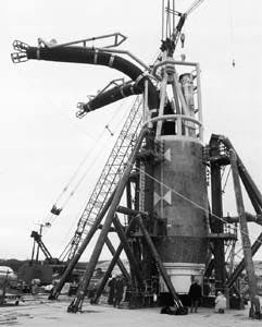
The riser bundles are lightweight concrete cylinders into which pipeline risers are embedded together with steel outfitting for installation/protection, support, and arrangements to seal off the tunnel from the sea (Fig. 3)(37715 bytes).
The tie-in spools have a complex three-dimensional configuration to accommodate the seabed and interfacing risers/pipelines. Rock-dumping was used to improve foundation conditions for the spools and hyperbaric welding equipment and also to facilitate expansion movements (Fig. 4)(43707 bytes).
TIN-IN DESIGN APPROACH
It was recognized early that the tunnel tie-in design had to be viewed in a wide perspective:
- The tunnel and offshore pipeline routing would sig nificantly affect the possible tunnel-piercing and tie-in.
- Piercing options (vertical/horizontal, blasted/ drilled) and tie-in methods (direct pull-in or spools and hyperbaric welding) would affect the tunnel and pipeline routing and produce different requirements for rock conditions, seabed sediments, and bathymetry.
Four interrelated areas of design were consequently defined:
- Offshore pipeline routing
- Seabed expansion loops, rock-dump support, and tie-in facilities
- Vertical tunnel piercings and prefabricated riser bundles
- Piercing branch tunnels and tunnel pipelines.
Three key parameters for the design development have been: 1. Piercing-point selection in view of the need for compact and homogeneous rock with a minimum of sediment cover. 2. Pipeline routing and spool configuration with respect to total number of pipelines including future lines, schedule of installation, and offshore destination; offshore pipeline corridor location; expansion control; space for installation and tie-in; and bathymetric and soil conditions for loop design, installation, and tie-in. 3. Tunnel routing with respect to rock conditions/weakness zones, inclination limitations for construction work, minimum rock cover, water depth of less than 180 m in view of diving regulations, pipeline expansion control.
Extensive subground and seabottom surveys provided required information for the design work. These surveys included acoustic profiling and bathymetric mapping, cone penetration tests and core drilling, refraction seismic of the rock mass, and ROV video survey.
Vertical piercing was selected mainly because of the seabed bathymetry/rock conditions and the number of pipelines.
Experience for subsea piercing construction is found in hard-rock tunneling in Norway. More than 300 underwater tunnel piercings have been carried out in Norway over the last 90 years to tap natural and artificial lakes for the water supply to hydroelectric power plants.
Before Troll Phase I, maximum water depth for a tunnel piercing was 105 m in 1974. The three Troll Phase I piercings at about 160-170 m water depth are thus a significant advance. In addition, this work included the first ever vertical piercing with preinstalled constructions in the shaft just below the final blast.
The design consists of two vertical shafts for the main tunnel and one for future use for a secondary tunnel. The shaft subdivision has been selected to minimize shaft cross-section, accommodate different pipeline expansion characteristics, and give space for initial and future seabed and tunnel pipeline installation work.
CONSTRUCTION
Tunnel tie-in construction consisted of vertical piercing; riser, rockdump and spool installation; and hyperbaric welding. 1. Tunnel, vertical shaft excavation. The subsea tunnel was excavated by traditional drill and blast. Loose seabed sediments at the piercing points were removed by a large underwater jetprop.
Rock masses between tunnel and seabed were mapped by test- hole drilling in order to detect water leaks and to map the rock surface and remaining sediment cover in detail. Correlation between tunnel and seabed coordinates and mapping was established by drilling a marking rod through to the seabed.
A safety barrier (steel gate) was installed to prevent flooding of the tunnel in case of excessive leaks during further work.
The vertical shafts were then excavated by careful blasting until a rock plug of only a few meters remained to the seabed. 2. Shaft outfitting and temporary tunnel plug construction. The required outfitting to support the riser bundle and enable
concreting for shaft sealing was mounted.
Fig. 5 (91053 bytes) presents the sequence of plug installation, blasting, and riser-bundle installation.
A temporary concrete plug, designed to withstand the final blast and equipped with the required piping, cabling, and access penetrations, was established 20-30 m from the piercing shaft. 3. Final blast. The final blast was drilled and charged.
The piercing chamber was partly flooded and pressurized, and the piercing blast executed. 4. Riser bundle installation. A marine installation vessel lowered the precast riser bundle plug with embedded riser pipes into the shaft to rest on the premounted shaft outfitting and provide temporary shaft sealing. 5. Annulus concreting. The annulus around the riser bundle plug was filled with concrete/grout injection via pipes from the dry side of the tunnel plug to seal the shaft permanently. 6. Piercing chamber drainage. The piercing chamber was dewatered by piping in the tunnel plug. This operation could also have been performed before annulus concreting, if found necessary. 7. Tunnel pipeline tie-in. The safety barrier, temporary tunnel plug, and the muck pile from the final blast were removed, followed by tunnel pipeline installation and tie-in of the vertical risers in the shaft.
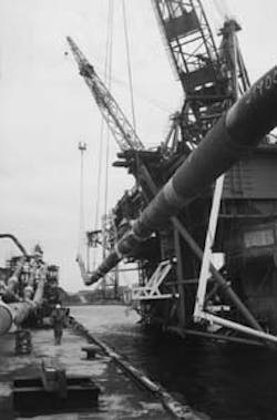
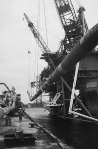
Following pipeline commissioning, a permanent tunnel plug was reinstalled to create a double barrier for the operational phase. 8. Rockdump construction. The seabed in the spool and offshore pipeline tie-in area was reinforced by crushed rock, installed by a dynamically positioned fall-pipe vessel. 9. Spool transportation and installation.Following final assembly at a nearby site, the spools were transported offshore hanging alongside a semisubmersible construction vessel (Fig. 6)before they were lowered to the seabed, along a guide wire to the riser, using a two hook, six-to-eight sling arrangement (Fig. 4)(43707 bytes). 10. Spool to riser tie-in. The air filled spools were aligned to the fixed riser, the habitat was installed on temporary support platforms, and the hyperbaric weld performed. 11. Offshore pipelay. The offshore pipeline was installed along the spool to a pipeline tie-in leg to ensure over length relative to the tie-in position.
A pipe catcher was preinstalled on the spool to protect it and ensure the correct lateral positioning of the pipe relative the spool. 12. Spool to pipeline tie-in. The pipeline was cut, lay-down head and pipe catcher were removed, and the pipe and spool aligned by H-frames before the habitat was set and the hyperbaric weld performed.
SUBGROUND CONSTRUCTION
The main subground structural arrangements for the tie-in construction included installing the riser bundle, piercing shaft outfitting for riser bundle support and annulus concreting, and tunnel plugs.
RISER BUNDLE
The objective of the riser bundle is to provide a structure for securing the riser pipes during installation and operation and also to create an initial sealing of the piercing shaft.
Two riser bundles, one for each of the main tunnel piercings, have been installed. The design is identical except for the risers.
The bundles have an overall height of approximately 20 m including a 9 m high, 5 m diameter lightweight concrete plug. The weight in air is about 450 metric tons (Fig. 7)A centralizing structure in the form of two orthogonally oriented, vertical trusses, was also fitted to the lower end of the riser bundle to ease lowering into the piercing shaft.
A 1 m OD titanium water in-take pipe penetrates the riser plug in addition to the risers. This pipe will provide water circulation within the tunnels when they are flooded for pipeline operation.
The lower end of the concrete plug is fitted with a machined steel cone which is to fit into another steel cone premounted in the piercing shaft. These cones, together with a rubber seal and injection arrangements, provided initial sealing of the shaft, before annulus concreting.
A lifting structure and a protection arrangement for the water in-take pipe is fixed to the upper end of the concrete plug. A ring beam with support points for eventual habitat platforms has been included to ease execution of the hyperbaric tie-in.
SHAFT OUTFITTING
The objective of the shaft outfitting is to provide instal- lation guiding and support for the riser bundle and to enable annulus concreting. The premounted installations must also be designed to resist the impact from the final blast.
The "female" steel cone is embedded in a reinforced concrete lining which is anchored by rock bolts (Fig. 5a)(91053 bytes).
Piping and injection hoses for annulus concreting and grout injection are also embedded in the concrete lining. These lines run from the dry side of the tunnel plug and terminate above the steel cone.
TUNNEL PLUGS
There are three plugs with different functions for each piercing.
A safety barrier in the form of a steel gate fixed in concrete lining was established to prevent tunnel flooding in excessive leaks during excavation of the piercing shaft.
A temporary tunnel plug of concrete was constructed to seal the tunnel during the final blast. The plug was fit-ted with piping for flooding and pressurizing the piercing chamber before the final blast and subsequent dewatering.
It also included piping for annulus concreting and cabling for the final blast ignition and some instrumentation.
The safety barrier and temporary plug were removed before tunnel pipeline installation.
A permanent tunnel plug was constructed upon completion of tunnel mechanical outfitting. This creates a second barrier towards the sea in addition to the riser bundle/annulus concreting.
SEABED CONSTRUCTION
Seabed tie-in construction involved tie-in spools, tie-in equipment (hyperbaric weld spread) and temporary arrangements, and rock dumping.
TIE-IN SPOOLS
Tie-in spool dimensions are heavily influenced by the preferred locations of the offshore pipeline corridor and the piercing points.
These locations are again governed by terrain features in the nearshore area and the piercing demand for good rock quality with a minimum of sediment cover.
The spool tie-in areas are characterized by 10-15 m of very soft clay at the offshore pipelines and by inclined seabed with thin layers of moraine and soft clay at the tunnel risers.
The spool layout is furthermore to accommodate seabed bathymetry with 1520 m elevation variation along the spools, expansion-induced stresses within code requirements, fixed riser tie-in stubs with 45 intermediate horizontal angles, and hyperbaric welding equipment requirements.
The resulting spool configuration has an overall length and weight in air in the range of 135-160 m and 130-180 metric ton, respectively.
Despite the size, installing the spools in one piece was preferred. This reduced lifting operations in the vicinity of the risers, eased the loop handling in view of the seabed bathymetry and sediments, and provided the most cost-efficient solution with significant scheduling advantages.
TIE-IN
The spools were tied-in to the risers upon set down prior to offshore pipelay. The offshore line tie-ins were performed sequentially as the lines were laid.
Norwegian-based Pipeline Repair System (PRS) was used for the tie-ins. This was the first job for the upgraded, newly built H-frames and habitat. The welding is fully automatic, while divers are used for equipment set up.
At the riser end, the sloping seabed and narrow riser spacing has introduced the need for habitat-support platforms. A large (20,000 hp) jetprop was used to clean the seabed for boulders and loose sediments prior to piercing, thereby also improving the habitat platform support conditions.
The riser structure is equipped with an interface beam with guidewire connections for precise set down and positioning of the platforms. The contractor preferred, however, to install free standing and more easily retrievable platforms.
Guidewires were used for habitat and spool installation to ensure precise set down and to reduce the risk of accidental impact loads. The spool-to-riser alignment benefitted from an airfilled spool weight of typically 10-20 metric tons.
At the offshore end, a pipe catcher was used to fix the lateral position of the pipeline, and lighter H-frames with greater mud-mats were introduced in order to reduce foundation loads/stresses. The weight of the flooded line and the H-frames, however, creates critical loads on the seabed/rockdump.
ROCKDUMP
The main objectives of rockdump construction are to improve the foundation conditions for the tie-in equipment and to ensure spool functionality during operation.
Virgin seabed bearing capacities for vertical load were typically 0.5-1.0 metric tons/sq m in the area for the spool-to- offshore line tie-in. This could further be reduced to half the value for horizontal loads.
The rockdump design has aimed to provide a minimum vertical load capacity of 2.5 metric tons/sq m for tie-in equipment.
The rockdump configuration is defined by several connected surface "planes," which reflect the straight sections of the spools and the offshore pipeline and the required counterfills.
Rockdump design has been a compromise between the wish to maximize its load-bearing capacity and simplify the surface configuration, which leads to increased thickness, volume, and cost, and the need to limit the thickness to avoid excessive counterfills for stabilization of the main fill and limit settlements of the underlying clay (which will continue to develop for the design life of 50 years).
A minimized thickness furthermore reduces pipe free spans from the rock-dump edge and finally limits volume and costs.
Strict vertical dumping tolerances have been applied. This is to provide the best possible support elevation for the spools relative to the fixed risers and because the tolerances would affect the support capacity, following their relative effect on the limited nominal thickness.
Precise survey data are of extreme importance.
The rockdump has been constructed in two phases: the baselayer is first made by a 1-5 in. grading, then the refined topping is made up by a 1-3 in. grading.
The construction procedures have focused on work sequencing to ease the tolerance fulfillment, while ensuring temporary stability of the rock berms and avoidance of the risk to entrap soft material inside the rockdump.
1996 FIRST GAS
The Troll Phase I piercing area design and construction constituted a complex engineering interface.
Topics range from rock tunneling and subsea blasted piercings with premounted shaft installations to prefabrication of riser bundles with their lightweight concrete plugs to marine operations for the installation of the bundles with subsea concreting for shaft sealing and, finally, to installation and tie-in of pipelines and expansion loops both in the tunnel and on the seabed.
Significant differences exist in the work approach (planning and execution) from tunneling to offshore work.
Traditional Norwegian rock tunneling is characterized by a certain amount of "detail engineering at site" which is in contrast to detailed mechanical design with long procurement and fabrication as well as offshore installation planning schedules.
All subground work and seabed rockdumping was completed in 1994.
The spools were installed and tied-in to the risers in early spring of this year and tied-in to the offshore lines in the autumn.
Commissioning will occur and first gas will flow in April 1996; sales gas will flow in October 1996.
ACKNOWLEDGMENT
The authors wish to thank A/S Norske Shell for the per- mission to publish this article.


