CROATIAN REFINER MEETS WASTE WATER TREATMENT STANDARDS, REDUCES FINES
Alan L. Meier
Krofta Engineering Corp.
Lenox, Mass.Ognjen Nikolic
INA Oil Refinery Rijeka,
Croatia
A new approach to waste water treatment at a refinery in Croatia produces effluent that not only meets the region's regulations for disposal into the Adriatic Sea, but also sur- passes the refinery's specifications for recycling process water.
Key to the dramatic reduction in pollutants was the installation of a Sandfloat unit developed by Krofta Engineering Corp. The Sand-float unit is a dissolved air flotation clarifier that combines flocculation, flotation, and multilayer filtration to produce high-quality effluent. In fact, the effluent from the unit has a lower hydrocarbon concentration than water from the underground wells that supply process water to the refinery.
While similar systems have been used for decades in industrial applications, this is the first time a Sand-float unit has been installed in an oil refinery.
THE PROBLEM
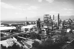
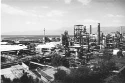
The 150,000 b/d INA refinery is located on the Adriatic Coast in Rijeka, Croatia. This area continues to derive most of its income from tourism, even though it is on the doorstep of the region's bloody war.
Maintaining that source of revenue is vital to the local government. Because of environmental pressures from the government, INA had to severely reduce the hydrocarbon content of the effluent it discharged to the sea.
Under current Croatian law, the hydrocarbon content of effluent discharged to the Adriatic Sea has to be less than 10 rag/1. In late 1995, the acceptable level will be reduced to 5 mg/1.
Before installing the Sand-float unit in November of 1994, the refinery effluent was treated in an API separator. The hydrocarbon content of the effluent ranged from 10 rag/1. to 60 mg/1.
Although the maximum allowable concentration is 10 mg/l., penalties are levied for discharges containing as little as 0.2 mg/l. hydrocarbons in effluent water. Table 1 (14161 bytes) shows the penalties for various concentrations of oil in refinery effluent water.
Under Croatian law, penalties are assessed based on the type and amount of pollutant in the effluent. Because the concentrations of phenols, sulfides, chemical oxygen demand (COD), and biological oxygen demand (BOD) in the refinery effluent were negligible, it was vital for INA to minimize the amount of oil in the effluent to further reduce overall fines.
Between 1989 and 1994, the refinery paid fines of DM1.0-1.5 million/year.
REFINERY OPERATION
The refinery produces lubricants, waxes, bitumen, and fuel oils. It employs processes including vacuum distillation, deasphalting, dewaxing, ferrofining (a hydrogenation process), methyl isobutyl ketone extraction, and bitumen blowing.
Underground wells provide process water with low levels of oil and ammonia.
Fig. 1 (99572 bytes) shows a flow diagram of the refinery.
The refinery produces four types of waste water:
- Process (oily) waste water
- Rainwater
- Cooling water blow-down
- Municipal waste water.
Under current operation, municipal waste water is segregated from other types of effluent and is channeled to the town's waste water treatment system. Rainwater and cooling water blowdown are treated in the API separator, but they also may be channeled through the Sandfloat unit, provided that the overall flow level does not exceed the Sandfloat's capacity of 1 million gpd (3,800 cu m/day).
Treatment of the process water begins when raw effluent waste water, with a hydrocarbon content of 1,000 mg/1. or greater, flows into the API separator. Effluent emerges from the separator with a hydrocarbon content of 10-60 mg/1.
Effluent from the API separator becomes influent for the 20- ft diameter SAF-BP 20 Sandfloat unit, which reduces the hydrocarbon concentration of the stream to 0.341.8 mg/1. (Table 2)(30266 bytes). This concentration is well within current and near-future discharge regulations.
Effluent from the Sand-float can be recycled and used as process water, or discharged into the sea.
SANDFLOAT OPERATION
Water emerging from the API separator is first treated with chemicals to induce flocculation. It is then pumped through directional inlet nozzles in the bottom of the Sandfloat's central flocculating tank. These nozzles impart a low-velocity, circular flow to the waste water, which provides the gentle mixing required to allow the remaining impurities to form flocs as the waste water rises in the tank.
Located near the top of the flocculation tank is Krofta's dissolved-air release mechanism. This device produces microscopic bubbles that adhere to the flocked impurities and cause them to float to the surface. A rotating scoop then removes the concentrated impurities (sludge) and empties them into the central collector.
For final cleansing, the waste water passes through an 11- in. deep bed of hydroanthracite and fine sand for a final filtering and polishing. This process traps any impurities not removed by the flotation process. After filtration, the clarified water is held in a compartment under the sand before being removed from the Sandfloat.
Flotation sludge and sludge from the sand filter are collected in a single tank and pumped to the API separator. Oil is skimmed from the collection tank and sent to the slop line.
The high efficiency of the sand is maintained by continual on-line backwashing. The filter, which surrounds the central flocculation tank, holds the sand and anthracite in a number of adjoining, isolated cells.
When the unit is operating, one section of the sand filter can be backwashed without interfering with the filtration process under way in the other sections. This is possible because a hood is lowered over the section to be backwashed, and filtered water from below is pumped up through the sand and anthracite to wash out impurities.
Backwash water is then recycled through the flocculation tank and treated again. The frequency and duration of cell backwashing can be preset and adjusted to suit process conditions.
TREATMENT COSTS
Capital investment for the new effluent treatment system, including piping, housing, and other civil works, was $3.5 million. This price was comparable to the alternative systems evaluated, but the Sandfloat was selected for two reasons:
- Space at the refinery was limited (the flotation and filtration equipment, including utilities, required only a 30 x 15 m area)
- No other supplier of dissolved air flotation equipment would guarantee less than 5 mg/1. of residual oil in the effluent after filtration.
- Electricity costs - $0.048/cu m or $76,800/year
- Chemical costs - $0.15/cu m or $24,000/year.
The refinery is saving about DM500,000/year in discharge penalties. At this rate, project costs will be paid out in 4 years.
RECYCLING
The decision to recycle the effluent as process water came about after pilot-plant tests of the Krofta system. In 5 weeks of pilot-plant testing, every sample of effluent from the unit contained less than 1 mg/1. of total hydrocarbons.
Because the filtered waste water is of such high quality and meets current and near-future regulations for waste water disposal, INA can recycle the water in a number of ways. It can be pumped into underground wells on site, pumped into the facility's hydrant system, or stored for future fire protection.
The water also is of high enough quality to be used in the refinery's cooling water system, but its temperature is too high.


