Early detection of custody-transfer gauge issues keys successful use
Luiz Gustavo do Val
James C. Hassell Jr.
Ali Al-Qahtani
Saudi Aramco
Dhahran
Proper calibration can yield savings of 0.4% over the typical 25-year life of a large natural gas transfer metering system, equaling $120-330 million of extra revenue for the system examined, depending on commodity pricing. Determining early that meters are properly calibrated is key to realizing these savings.
Different manufacturers specify different inlet requirements for custody-transfer ultrasonic gas flow meters. Traditional designs usually require relatively long inlet piping and a flow conditioner. Organisation Internationale de Metrologie Legale (OIML) R 1371 forces ultrasonic flow meter (UFM) manufacturers to develop newer state-of-the-art devices to meet its Class 0.5 performance requirements. The maximum error allowable due to installation is ± 0.17%, almost half of what is required by the American Gas Association (AGA) and International Standards Organization (ISO) 17089-1.
The newer meters operate with short inlet piping lengths and no longer require a flow conditioner, immediately reducing space, weight, and overall material costs. Longer-term benefits include cost savings from avoiding the pressure drop created by the flow conditioner's removal, eliminating performance-loss from fouling of the flow conditioner, and performing periodic calibration at the test facility without having to send both the field calibration spool and its attached flow conditioner.
Several meter-design parameters affect ultrasonic flow measurement accuracy:
• Number of paths.
• Path type, direct or reflective.
• Path locations.
• Paths in one or different planes.
• Paths of different lengths.
• Average flow velocity calculation method.
Custody transfer meters normally have four to eight paths, either reflective or direct, in one or two planes. Meter design can aim to achieve high accuracy, high flow-disturbance tolerance, and self-checking diagnostic data. The ideal design would include all these criteria, but this may not be feasible and explains why such a large variety of meter designs exist.
Three different approaches have evolved to meet operational preferences:2
• Approach 1: Installation of a flow conditioner to establish a flow profile. Adequacy of the profile is confirmed using meter diagnostics, which then validate meter accuracy. A reduced bore can also act as a flow conditioner.
• Approach 2: Designing the meter to detect flow disturbances and be immune from them, confirming its accuracy.
• Approach 3: Designing the meter to measure profile factor, swirl, cross flow, distortion, and turbulence and using them to correct flow measurement.
The price for Approach 1 is the cost of pressure drop caused by the flow conditioner and loss of performance if the conditioner becomes fouled. Any changes to the flow conditioner design defeat the purpose of its installation. The advantage of Approaches 2 and 3 is elimination of flow conditioners.
Requirements
AGA 93 states in Section 7.2.3:
"Changes in internal diameters and protrusions should be avoided at the [ultrasonic meter] UM inlet because they create local disturbances to the velocity profiles. The UM flanges and adjacent upstream pipe should all have the same inside diameter, to within 1%, and be carefully aligned to minimize flow disturbances, especially at the upstream flange section. The adjacent upstream flange internal welds should be ground to a smooth transition with the pipe wall."
ISO 17089-14 states in Section 5.9.3.3:
"Changes in inside diameters and protrusions should be avoided at the [ultrasonic meter] USM inlet to avoid the disturbance of the velocity profile, unless the meter is classified as "reduced bore", see 5.2.4.
The flanges and adjacent upstream pipe shall be straight, cylindrical, and have the same inside diameter throughout as the inside diameter of the inlet of the meter, preferably within 1% but at maximum within 3%. These components shall be carefully aligned to minimize flow disturbances, especially at the upstream flange."
Item C from the same section says:
"For a minimum upstream length of 2D, there shall be no flow disturbances from flanges, flow straighteners, etc. Over a length of at least 10D or Lmin upstream of the meter, whichever is smaller, the pipe section(s) shall fulfil the following requirements: c) the internal weld of the downstream flange of the upstream piping shall be ground smooth and no part of the upstream gasket or flange face edge shall protrude into the flow stream."
AGA 9 states in its Section 6.4:
"The metering package will consist of the ultrasonic meter, adequate upstream and downstream piping, as defined in Section 7.2.2, along with thermowell(s), sample probe, and any flow conditioning to ensure that there is no significant difference between the velocity profile experienced by the meter in the laboratory and the velocity profile experienced in the final installation. It is a requirement that all custody transfer metering packages be flow-calibrated in a flow calibration facility or by a calibration system that is traceable to a recognized national/international standard."
ISO 17089-1 states in Section 6.3.1:
"All Class 1 meters shall be calibrated under flowing conditions during which the meter shall not generate any critical alarms. For Class 2 meters this flow calibration is highly recommended. The calibration of meters under flowing conditions (flow or flow calibration) may also be required because of: national legal requirements, high accuracy requirements, the application for custody transfer."
Item H from section 6.3.2.1 states:
"To minimize the uncertainty of the calibration, the calibration shall be conducted: h) whenever possible, by using the upstream and downstream meter spools or dedicated calibration spools and flow conditioners (when applicable)."
Correction measures
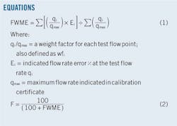
The flow-weighted mean error (FWME) factor allows corrections using a single calibration factor. A single-calibration factor technique will be used later in this article to evaluate calibration of a given meter with two different piping finishes.
If a UFM's flow measurement output is linear over the operational flow range of the meter, the FWME correction method can minimize the meter's measurement bias error. If a UFM's flow measurement output is nonlinear over the meter's operational range, more sophisticated error correction techniques can be applied.
Equation 1 calculates FWME for calibration data.
Applying a single calibration factor, F, to the meter output reduces the magnitude of the measurement error. Equation 2 calculates F.
Project execution
This section identifies issues associated with poor project execution in manufacturing upstream and downstream meter spools for a 720 MMscfd ultrasonic gas metering system. The project's function specification design (FSD) document specified the system consist of three 18-in. meters run in Z-configuration: two duty meters and one check meter for the duty meters.
The FSD stated that each meter run shall have:
• Inlet isolation; double block and bleed valve.
• Two-section upstream meter tubes with total minimum clear length of 20D and a flow conditioning plate installed midway.
• An ultrasonic flow meter.
• A pressure transmitter.
• Downstream meter tubes with minimum clear length of 5D.
• Two thermowells installed 5D downstream of the meter, one for a resistance temperature detector connected to a temperature transmitter and one for checking purposes.
• A 2-in. flanged inspection fitting downstream of the thermowells, mounted at 45° facing the flow.
• Z-configuration installation of the meter run, with double block and bleed valve isolation to allow series operation between the duty meter and check meter.
• Meter-run outlet double block and bleed valve isolation.
The system integrator responsible for its fabrication also was required to ensure that:
• All meters be flow-calibrated with their meter tubes and flow conditioners.
• The upstream and downstream meter tube sections be constructed of seamless pipe.
• Flanges and fittings welded to meter tubes have internal weld joints ground to a smooth finish, flush with the pipe ID and free of sharp edges or abrupt changes in surface level or diameter.
• Upstream meter tube ends be flanged and equipped with a spacer ring or jack screw so that the tube sections and the flow conditioner can be easily removed for inspection and cleaning.
Inspection
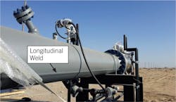
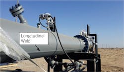
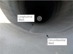
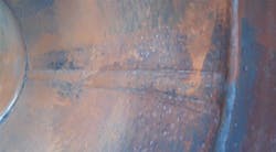
An inspection performed in 2014 on the metering system found non-conformities against the FSD. Longitudinal seam-welded 18-in. pipes had been used both upstream and downstream of all three meter runs. The longitudinal seams were also not ground smooth from inside (Figs. 1-2).
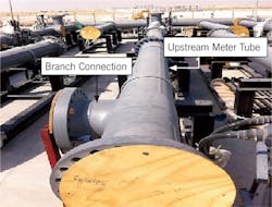
Two of the upstream meter tubes were also found without the flanges required on the upstream end for easy inspection and cleaning (Fig. 3). The branch connection in Fig. 3 is to connect the Z-configuration pipe spool. The arrangement shown, however, prevents removal of the upstream meter tube and flow conditioner for cleaning inspection and calibration.
Inspection could not find the flow conditioning plate's installation marking. This marking is required to ensure the flow conditioner will be installed in the same orientation after dismantling the upstream meter tube for factory flow calibration or whenever the conditioning plate is taken out for inspection or cleaning.
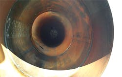
After hydrotesting, the spools were not internally protected by non-toxic vapor phase corrosion inhibitor (Fig. 4). Internal circumferential girth welds were also not grounded and flushed with the pipe wall (Figs. 4-5).
In addition to the inspector's report, the measurement engineer identified non-conformities. Two of the three meter runs were not calibrated with the actual meter tubes installed upstream of the flow conditioner. Two of the three meter runs had also not been calibrated with the actual downstream meter tubes.
The system integrator responded to the inspection report in defense of the services it had supplied. The accompanying box shows the salient portions of this response. The senior UFM engineer also mentioned through an e-mail that the meter's performance in the flow lab is not affected by calibration with different meter tubes upstream of the flow conditioner and downstream of the meter.
Decision taken
Measurement engineers decided to:
• Fabricate new seamless upstream and downstream meter tubes as per the FSD.
• Require the new upstream and downstream meter tube ends be flanged.
• Mandate that all flanges and fittings welded to meter tubes have internal weld joints ground to a smooth finish, flush with the pipe ID and free of sharp edges or abrupt changes in surface level or diameter.
• Recalibrate all three meters with their upstream and downstream meter tubes and flow conditioners.
• Make each meter run's marks show alignment of the flange and flow conditioner tested when each is recalibrated.
• Mandate internal application of non-toxic vapor phase corrosion inhibitor after any hydrotest or flow calibration, as specified in the FSD.
The system integrator implemented these actions in 2015.
Calibration results
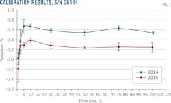
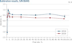
Figs. 6-8 show the calibration certificate results obtained from NMi Euroloop Gas Calibration for all meter runs before and after implementation of the measurement engineer's corrective actions. Each chart plots the meter deviation from the calibration standard vs. the percentage of the maximum flow rate.
On all meters the 2015 calibration differences are less than the 2014 differences. The uncertainty bars for given flow rates also do not overlap, indicating a systematic error (bias) due to poor engineering practices in fabricating the 2014 meter tubes (spools).
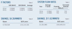
To better visualize the magnitude of bias introduced by the meter tubes, Table 1 presents the single calibration factor (F) and the flow-weighted mean error (FWME) for each meter by year. The variation presented in Table 1 is the F-factor's percentage variation between 2015 and 2014.
Meters 06643 and 06444 are used for customer billing. Meter 06445 is the check meter used only for verification of the billing meters.
F is a single calibration factor applied to the meter output to reduce the magnitude of the measurement error. Table 2 presents the average F factor for meters 06443 and 06444 by year before and after corrective actions.
Applying the average F factor for the daily flowrate of the metering system, 720 MMscfd, yields the results shown in Table 3. The natural gas seller will charge for an additional 3 MMscfd due to the corrective actions put in place when fabricating the meter tubes.
Using a high heat value (HHV) for the natural gas of 1,036 btu/scf and the European international price of $4.20/MMbtu in place in March 2016,5 Table 4 shows the money recouped to the seller over the standard 25-year lifetime of a gas metering system: almost $5 million/year or almost $120 million over 25 years. Assuming, however, an average European international price for natural gas of $11.62/MMbtu as observed between October 2011 and October 2013,5 when oil was near $100/bbl, revenue recouped would have equaled $13 million/year or almost $330 million over 25 years (Table 5).
References
1. OIML R 137, "Gas meters, Part 1: Metrological and technical requirements" and "Part 2: Metrological controls and performance tests," 2012.
2. Do Val, L.G, "The impact of the use of OIML R 137 ultrasonic gas meters of Class 0.5 in the hydrocarbon industry," OIML Bulletin, Vol. 57, No. 2, April 2016.
3. AGA 9, "Measurement of Gas by Multipath Ultrasonic Meters," 2007.
4. ISO 17089-1, "Measurement of fluid flow in closed conduits-Ultrasonic meters for gas Part 1: Meters for custody transfer and allocation measurement," 2010.
5. European Union Gas Import Price, https://ycharts.com/indicators/europe_natural_gas_price.
System integrator
"Dear Sir, We confrim receipt of your detailed inspection report with deviations....
We are convinced that the skid which we supplied is perfectly fit for the intended purpose, i.e. accurate gas measurement, and lives up to good engineering practice.
We have, however, commented on each individual remark and are aiming at finding an acceptable solution for each point at the soonest ..."
System integrator's senior UFM engineer
"...According to the FSD the use of welded pipe for meter tubes is allowed only for 24-in. size and larger. However, internationally accepted standards like AGA 9 and ISO 17089-1 allow the use of welded pipe for all sizes as long as the meter tubes comply with the applicable requirements to avoid disturbance of the gas velocity profile (AGA 9 §7.2.3 and ISO 17089-1 §5.9.3.3).
It can be assumed that the use of welded pipe has no effect on the measurement accuracy of the ultrasonic meters because:
• The meter tubes comply with AGA 9 and ISO 17089-1.
• The upstream meter tubes after the flow conditioner have been included with the calibration (AGA 9 §6.4).
• The calibration results comply with AGA 9 §5.1...."
Recommendations
1. Require a qualified inspector review the metering system manufacturer before the system is delivered to the field. This occurred for the subject project, but the deficiencies found by the inspectors in the field were not detected by the contract inspection company at the manufacturer's site, despite the FSD clearly stating all engineering requirements. As the scope of inspection is large and involves many disciplines including flow metering, either the overseas inspector (or company) should be adequately trained for the system or the project metering engineer should be part of the inspection team.
2. Use newer state-of-the-art gas ultrasonic meter designs. Usually, these newer meters can operate with short inlet lengths and don't need a flow conditioner. These meters can be calibrated in a lab with the lab's pipe spools (upstream and downstream) since the IDs of the upstream calibration spool have the same ID as the inlet of the meter within ±3%. The authors recommend ±1% as good engineering practice. Also, a careful alignment of the meter with its upstream calibration spool is very important. This process will reduce the project's delivery time, logistics, and associated costs. These provisions allow the meter's spools to be manufactured in the place or country that the meter will be installed, eliminating the need to send the meter spools (and flow conditioner if required) for meter calibration. This idea approach also applies to the meter's periodic recalibration. Again, the ID of the field upstream meter tube shall be the same as the diameter of the inlet of the meter within ±1%. Careful alignment is required. The three meters mentioned in this article were not state-of-the-art and therefore required long inlet lengths and a flow conditioner, demanding calibration of the whole metering package.
3. For an ultrasonic meter requiring a flow conditioner, calibrate the meter with its meter tubes, flow conditioner, and thermowells. After completion of meter calibration, ensure each meter run is marked to indicate alignment of flanges and flow conditioner at the time of calibration. Some manufactures specify that only the meter's flow conditioner and the upstream pipe tube between the flow conditioner and the meter itself need to be sent to the lab.
4. Meter tubes with seamed pipe shall have internal longitudinal and circumferential welds machined to a smooth finish, flush with the internal diameter of the pipe and free of sharp edges or abrupt changes in surface diameter. If not machined, never agree that the meter has been calibrated with its pipe spools as a single package. This argument has been discredited and an average calibration shift of +0.4% reported. Avoiding this calibration shift represented a large cost savings for the natural gas seller.
5. All flanges and fittings welded to meter tubes shall have internal weld joints ground to a smooth finish, flush with the ID of the pipe and free of sharp edges or abrupt changes in surface level or diameter.
The authors
Luiz Gustavo do Val ([email protected]) is metering engineer at Saudi Aramco, Dhahran. He has also served as metering consultant at Petroleo Brasileiro SA. He holds an MS (2001) in mechanical engineering from Pontificia Universidade Catolica do Rio de Janeiro. He is a member of the custody measurement standards committee of Saudi Aramco.
James C. Hassell Jr. ([email protected]) is an engineering consultant at Saudi Aramco, Dhahran. He has also served as a measurement specialist at Alyeska Pipeline Service Co.
Ali Al-Qahtani ([email protected]) is metering engineer at Saudi Aramco, Dhahran. He holds a BS (2015) in mechanical engineering from King Fahd University of Petroleum and Minerals, Dhahran.
