Flow simulations solve WHRSG vibration issues
Barbara L. da Silva
Celso Murilo dos Santos
Pedro Bianchi
Neto Henry
França Meier
Regional University of
Blumenau, Brazil
Eduardo Oliveira
Waldir Pedro Martignoni
Petróleo Brasileiro SA
Rio de Janeiro
Petróleo Brasileiro SA (Petrobras) has used computational fluid dynamics (CFD), an analytical simulation tool for studying fluid mechanics, to determine possible causes of and solutions to flow-induced vibrations (FIVs) in a waste heat-recovery steam generator (WHRSG) of the residue fluid catalytic cracking (RFCC) unit at its 53,000-b/d Capuava refinery (Recap) in Mauá, São Paulo, Brazil.
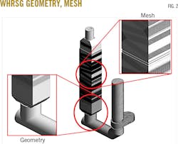
Petrobras used CFD modeling to simulate hot gas flow through the WHRSG's duct and boiler, designing a detailed three-dimensional geometry representing the real system with a roughly 15.5-million node mesh. To reproduce the most important structures of real turbulent flow, Petrobras adopted a Large Eddy Simulation (LES) of the WHRSG at its 100% and 80% rated capacities with a limit for the end of vibrations.
Results of CFD-based simulations and analyses led Petrobras to change duct geometry to smooth inlet flow into the boiler, minimizing pressure oscillations in the boiler's internal flow as a means of reducing FIVs.
This case study examines the benefit of using CFD numerical tools to analyze engineering problems in a refinery unit where obtaining measured data is not always feasible. The findings highlight the need to account for entrance effects in the design of WHRSGs, and heat exchangers in general, to prevent FIVs.
Background
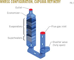
Petrobras has observed FIVs for flue-gas mass flow in Recap's WHRSG when operating near rated capacity since the unit's commissioning in 2001. The WHRSG has a vertical design, with an ascending path of flue gases traveling through the tube bundles. Gas flow into the unit is limited by an upstream diverter valve sending 20% of mass flow directly to the chimney to avoid damage resulting from the vibrations, decreasing heat recovery.
Fig. 1 shows the geometry and configuration of Recap's RFCC WHRSG.

Because WHRSGs are the main equipment used for heat recovery in RFCCs, they can present FIVs that lead to production losses, depending on operating conditions, in the same way FIVs in thermal equipment at large power plants commonly do.1 Interaction between hydrodynamic forces arising from flow and structural reactions cause this phenomenon.2
FIV mechanisms
Four main mechanisms are associated with FIVs: fluid elastic instability, periodic vortex shedding, turbulent buffeting, and acoustic resonance.
Fluid elastic instability occurs at flow rates above a critical velocity when the structure cannot dissipate enough energy received from the fluid via damping. It is the vibration mechanism that causes the most damage in the shortest period of time due to large vibration amplitudes, particularly with respect to cross-flow in tube bundles.3
Periodic vortex shedding vibrations arise when the vortex shedding frequency approaches the natural frequency of the structure, causing resonance. This phenomenon is frequently observed for cross-flow with single cylinders but can also occur in tube bundles for fluids with higher density.3
A single cylinder or tube array can estimate the vortex-shedding frequency using the Strouhal number vs. Reynolds number maps (or for tube bundles vs. pitch ratio).1 4 The Strouhal number is a dimensionless parameter that relates to a combination of three factors: flow velocity, vortex shedding frequency, and diameter or characteristic length.
Turbulent buffeting causes vibrations of very low amplitude and is associated with fatigue in long runs if other vibration mechanisms are avoided.5 For devices that operate with two phases, such as WHRSGs, turbulent buffeting results from differences in the material properties of the phases, phase-change processes, and complex interfacial interactions.2
The acoustic resonance mechanism is more common for gas inside a heat exchanger's shell and causes a loud noise as well as vibrations.5 It is similar to the periodic vortex shedding mechanism, though in this case, the shedding frequency approaches the natural acoustic frequency of the cavities between tubes.3
Pre-CFD approaches
In a first attempt to eliminate the occurrence of FIVs in Recap's WHRSG, Petrobras engineers began with the hypothesis that the vibrations stemmed from resonance between evaporator tube bundles and flow within the unit. They mapped operating frequencies externally to the unit equipment and compared those with natural frequencies of the tubes. The mapping of the most intense vibration frequencies showed measurements close to values pointing to periodic vortex generation and evaporator tubes shedding downstream.
As an initial solution, Petrobras proposed installing concrete baffles along with metal clamps, or bracers, to the tube bundles to change the WHRSG's natural frequencies. Difficulties associated with full-implementation of the project and lingering suspicions regarding other possible causes of the vibrations, however, led engineers to instead undertake a detailed numerical simulation of the equipment using CFD to obtain a complete diagnosis.

CFD
Alone or coupled with mechanical analysis, CFD tools, which study fluid flow using only numerical simulation, have been widely employed to examine the causes of and propose solutions for FIVs.6-14
A fusion of fluid mechanics and mathematical modeling techniques, CFD requires defining the geometry of a fluid-flow problem using nodes or cells within a mesh, defining boundary conditions and fluid properties, and solving resultant fluid-flow equations at each mesh cell or node (OGJ, Sept. 26, 1994, p. 92).
Several strategies can model the interaction between movement of tube bundles and flows passing through them, including Navier-Stokes equations to solve outer flow to tubes using the finite volume method and computed tube displacement to recalculate mesh at each time step. 10 11
An arbitrary Lagrangian-Eulerian approach can account for tube movement's influence on flow in a coupled manner.13 In this formulation, the boundaries consist of an arbitrary domain and their displacement occurs according to the flow forces. The approach specifically has studied vibrations in tube arrays with a square-pitch arrangement subjected to crossflow in three and two-dimensions, respectively, where the Reynolds number for flow was lower than 5,000.9-12
Because effects of tube movement on flow in situations where highly turbulent flow is present could be neglected, the LES approach ensures reproduction of the most important structures of real turbulent flow, as well as a subsequent analysis of mechanical effects on equipment.13 The LES approach, in particular, allows for acquiring transient results using Navier-Stokes equations to evaluate power spectral density and signals for the lower frequencies (large scales).14
Revised approach
Petrobras engineers recognized that understanding FIV required knowledge of the fluid dynamics inside the equipment in question, which in the case of complex equipment such as Recap's WHRSG, was impractical without CFD.
In its revised approach, Petrobras assigned greater importance to the idea that FIVs in the WHRSG resulted from vortex shedding, hypothetically due to sudden changes in flow direction imposed by the geometry of the duct directing hot gases to the boiler.
The revised study used CFD techniques to diagnose the causes of vibrations in the unit with the aim of analyzing velocity profiles and the power spectral density of the pressure in the region of interest, requiring adoption of an LES approach to simulate turbulence.
After identifying the probable cause of the FIVs in the equipment, the same techniques provided a prognosis and evaluated the resulting effects of proposed solutions.
High flow-turbulence only allowed engineers to address the fluid dynamics of the steam generator, leaving analyses of mechanical effects for postprocessing.13
Mathematical models
As part of the CFD study, Petrobras developed a detailed three-dimensional model using LES's approach to turbulence, in which large scales are solved by filtered Navier-Stokes equations. Smaller scales, which are more homogeneous and isotropic, were modeled through a subgrid model.
Equations 1 and 2 are filtered Navier-Stokes equations governing flow for large-scale simulations. Equation 3 governs the subgrid-scale Reynolds tensor (which includes the small-scale effects in the flow), and Equations 4 and 5 Boussinesq's hypothesis, which models the subgrid-scale Reynolds tensor with a turbulent viscosity.
The Smagorinsky-Lilly dynamic model (Equations 6 and 7) defines subgrid scale turbulent viscosity,.
The dynamic proportionality coefficient (Equation 6) is a function which adjusts to flow in time and space. Its expression is obtained by applying a second filter, or the test filter, represented by a circumflex (Equation 8).15 The dynamic proportionality coefficient, then, depends on known variables and is produced by a double-filtering process.
Because Petrobras considered compressibility of hot gases in flow a significant factor in FIV occurrence in Recap's WHRSG, the company included the filtered thermal-energy conservation equation in its model (Equation 9).
While the subgrid-scale enthalpy flux can be modeled with Boussinesq's hypothesis (Equation 10), Petrobras rewrote the equation by replacing the subgrid scale turbulent thermal conductivity with the definition of the subgrid-scale turbulent Prandtl number, thereby modeling subgrid-scale turbulent viscosity (Equation 11).
CFD simulation
Petrobras engineers prepared a hybrid mesh of around 15.5-million nodes for the unit's flue-gas domain (outside the tube bundles), including the gas-inlet duct and the diverter valve (Fig. 2). Engineers also used a finite-volume method to solve transient Navier-Stokes equations with the aid of a commercial code.
The same mesh simulated the steam generator at both its 100% and 80% rated capacity to investigate possible vibration causes. Both cases used a prescribed mass-flow boundary condition on top of the flue gas inlet duct and a prescribed gauge-pressure condition for the gas outlet at the WHRSG's top.
The boiling temperature of water plus 20° C. served as the temperature for the evaporators' external tube walls. The superheaters and economizer used a linear function of their heights based on WHRSG design data to estimate temperature.
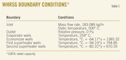
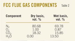
Table 1 reports boundary conditions for the WHRSG unit's rated capacity. Table 2 presents the composition and volumetric fractions of RFCC flue gas used for the simulation.
After simulation the engineer team set up pressure and velocity monitoring points to evaluate (particularly in the steam generator's gas inlet region) spectral density power, measured as the intensity of the oscillatory components constituting the signal received as a function of frequency.
Fig. 3 shows the designated main monitoring points used in the study.
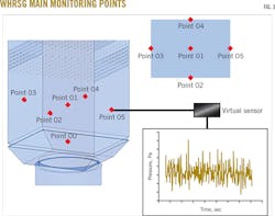
Engineers applied Fast Fourier transform (FFT) to evaluate dominant frequencies in the flow using temporal data.
In most cases, simulation processing required 512 cores of the computer cluster at Petrobras' Leopoldo Américo Miguez de Mello Research and Development Center (CENPES), Rio de Janeiro, and the cases advanced at a rate of about 2 sec/day of flow time, with each case maintained for at least 20 sec of real time.
Diagnosis
With the WHRSG simulated at 100% and 80% rated flue gas capacity to identify vibration causes, Petrobras obtained mean and standard-deviation velocity profiles as well as power spectral density for pressure signals at a few relevant points. Most flow instabilities were in the lower section of the generator.
Fig. 4 shows mean-velocity and standard-deviation profiles for flow instabilities in the WHRSG's lower section at 100% and 80% rated capacity.
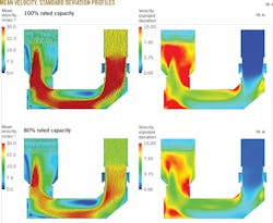
The flue-gas flow path created an asymmetric velocity profile, with fluctuations in both cases > 15 m/sec in zones close to the duct corners (sharp edges). Three recirculation zones (eddy structures) form at these sharp edges and in the horizontal section of the duct.
The flow downstream of the "T" is similar to the flow over a backward-facing step, which typically presents a recirculation zone right after the sudden expansion (step). While engineers reasonably postulated that the "T" may promote generation of a periodic vortex-shedding process related to structural vibrations, it did not discard the possibility of vortex shedding from the tube bundle as a contributor to FIV.
After reducing the unit's flue-gas flow rate to 80% rated capacity, engineers observed the same profiles obtained for the simulation at 100% rated capacity. The mean velocity and standard deviation at 80% rated capacity, however, both decreased, with a consequent reduction in fluctuation intensity.
Fig. 5 shows power spectral density plots for pressure at points p0, p1, p5 (Fig. 3), and a point 14 m above p0 (labeled p14m).
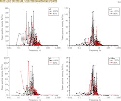
The signal magnitude for the case with a reduced rated capacity generally was inferior to that observed with full capacity, except for points near the walls, as exemplified by the pressure spectrum at point p5.
Table 3 shows both the frequencies with the highest degree of excitation for the 100% rated capacity case for points p0, p1, p5 and p14m and the frequency interval with greatest magnitude for both cases.
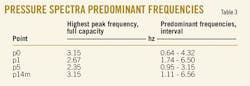
A prevailing frequency interval around 2-3 hz is common for all points, with the highest peaks at roughly 3 hz. The main natural modes of evaporator tube-bundle vibration were identified from the modal analysis as 3.83 hz and 11.82 hz. The similarity between the predominant frequencies of the flow and the first natural frequency of the tubes suggests a lock-in phenomenon. Synchronization close to 40% is likely between vortex shedding and natural frequencies, so shedding frequencies between 3.00 and 5.36 may excite the structure.16 The lack of vibrations at 80% rated flue-gas mass flow shows that the energy provided at these frequencies is not sufficient to excite the structure.
Prognosis
Considering Petrobras engineers' hypothesis that vibrations in the steam generator are caused by vortex shedding from the inlet duct structure, the team proposed two new geometries for the duct (Fig. 6). The first uses an elbow for the "T", keeping the sectioned curve of the duct, while the second replaces parts both after the diverter valve and before the steam generator with curves tangent to ground level. These proposed changes sought to avoid the backward-facing step vortex-shedding phenomenon by smoothing the flow. Both were simulated at 100% rated capacity for comparison with the original geometry.
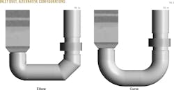
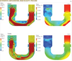
Fig. 7 shows mean-flow velocity and pressure profiles for the alternative inlet-duct configurations.
Substitution of the "T" with an elbow (Fig. 7a) eliminated only one of the recirculation zones. The one in the horizontal section remained and reduced flue-gas flow area while increasing velocity intensity. These results indicated greater instability and high-pressure regions where sudden changes in flow direction occurred.
The configuration with curves (Fig. 7b) provided a more organized flow and avoided sudden changes in flow direction. A greater number of recirculation zones were eliminated and the velocity intensity reduced, lowering flow instability at the WHRSG's entrance.
Petrobras engineers also examined flow fluctuations with the alternative inlet duct configurations based on the pressure spectrum for selected points.
Fig. 8 compares WHRSG fluctuation with the original duct ("T"), the duct with an elbow, and the duct with curves at 100% rated flue-gas capacity.
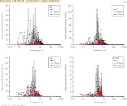
Predominant frequencies remained about the same for selected points. In the case of the duct with a "T" frequencies measured 2.35-3.15 hz, with elbows 1.22-3.02 hz, and curves 0.89-4.52 hz.
Pressure-oscillation magnitude dropped by up to 6.5 times in the case of the elbow duct and by up to 50 times with the curve duct. This result confirms inlet geometry's influence on instability and supports the initial hypothesis of vortex shedding from the backward-facing step as a contributor to FIVs in the unit.
References
1. Païdoussis, M.P., "Real-life experiences with flow-induced vibration," Journal of Fluids & Structures, Vol. 22, No. 6-7, August-October 2006, pp. 741-755.
2. Miwa, S., Mori, M., and Hibiki, T., "Two-phase flow induced vibration in piping systems," Progress in Nuclear Energy, Vol. 78, January 2015, pp. 270-284.
3. Pettigrew, M.J., Taylor, C.E., Fisher, N.J., Yetisir, M., and Smith, B.A.W., "Flow-induced vibration: recent findings and open questions," Nuclear Engineering & Design, Vol. 185, No. 2-3, October 1998, pp. 249-276.
4. Weaver, D.S., and Fitzpatrick, J.A., "A review of cross-flow induced vibrations in heat exchanger tube arrays," Journal of Fluids & Structures, Vol. 2, No. 1, January 1988, pp. 73-93.
5. Goyder, H.G.D., "Flow-Induced Vibration in Heat Exchangers," Chemical Engineering Research & Design, Vol. 80, No. 3, April 2002, pp. 226-232.
6. Cong, T., Tian, W., Qiu, S., and Su, G., "Study on secondary side flow of steam generator with coupled heat transfer from primary to secondary side," Applied Thermal Engineering, Vol. 61, No. 2, Nov. 3, 2013, pp. 519-530.
7. Ferng, Y.M., and Chang, H.J., "CFD investigating the impacts of changing operating conditions on the thermal-hydraulic characteristics in a steam generator," Applied Thermal Engineering, Vol. 28, No. 5-6, April 2008, pp. 414-422.
8. Huang, C.C., Hsieh, J.S., Chen, P.C., and Lee, C.H., "Flow analysis and flow-induced vibration evaluation for low-pressure feedwater heater of a nuclear power plant," International Journal of Pressure Vessels & Piping, Vol. 85, No. 9, September 2008, pp. 616-619.
9. Zhao, W., Xue, F., Shu, G., Liu, M., Lin, L., and Wang, Z., 2014. "Analysis of flow-induced vibration of steam generator tubes subjected to cross flow," Nuclear Engineering & Design, Vol. 275, August 2014, pp. 375-381.
10. Schroder, K., and Gelbe, H., "Two- and three-dimensional CFD-simulation of flow-induced vibration excitation in tube bundles," Chemical Engineering & Processing, Vol. 38, No. 4-6, September 1999, pp. 621-629.
11. Gohel, H.R., Shah, B.A., and Lakdawala, A.M., "Numerical investigation of flow induced vibration for the triangular array of circular cylinder," Procedia Engineering, Vol. 51, 2013, pp. 644-649.
12. Han, Z., Zhou, D., He, T., Tu, J., Li, C., Kwok, K.C.S., and Fang, C., "Flow-induced vibrations of four circular cylinders with square arrangement at low Reynolds numbers," Ocean Engineering, Vol. 96, Mar. 1, 2015, pp. 21-33.
13. Longatte, E., Bendjeddou, Z., and Souli, M., "Methods for numerical study of tube bundle vibrations in cross-flows," Journal of Fluids & Structures, Vol. 18, No. 5, November 2003, pp. 513-528.
14. Lam, K., Lin, Y.F., Zou, L., and Liu, Y., "Experimental study and large eddy simulation of turbulent flow around tube bundles composed of wavy and circular cylinders," International Journal of Heat & Fluid Flow, Vol. 31, No. 1, January 2010, pp. 32-44.
15. Lilly, D.K., "A proposed modification of the Germano subgrid-scale closure method," Physics of Fluids A, Vol. 4, No. 3, February 1992, pp. 633-635.
16. Han, X., Lin, W., Tang, Y., Zhao, C., and Sammut, K., "Effects of natural frequency ratio on vortex-induced vibration of a cylindrical structure," Computers & Fluids, Vol. 110, Mar. 30, 2015, pp. 62-76.
The authors
Barbara Louize da Silva ([email protected]) is a postgraduate student at the Regional University of Blumenau, Santa Catarina, Brazil, where she earned her BA (2014) in chemical engineering. She specializes in verification and validation in CFD and industrial applications in partnership with Petróleo Brasileiro SA (Petrobras). She previously worked as an intern at Petrobras, where she used CFD to address problems associated with petrochemical operations.
Celso Murilo dos Santos ([email protected]) holds a BS (2003) in chemical engineering from the Regional University of Blumenau, Santa Catarina, Brazil, and an MS (2005) in chemical engineering from the State University of Campinas, São Paulo, Brazil (2005). From 2006-15, he worked under contract for Petrobras, where he used CFD on oil refining and processing projects involving single and two-phase (liquid-gas and solid-gas) systems.
Pedro Bianchi Neto ([email protected]) is a postgraduate student at the Regional University of Blumenau, Santa Catarina, Brazil, where he earned a BS (2014) in chemical engineering. He specializes in verification and validation in CFD and industrial applications in partnership with Petrobras. He previously worked as an intern at Petrobras and the University of Bremen, Germany, where he focused on applying CFD to solve problems associated with the petrochemical industry as well as upscaling of nanoparticle production.
Henry França Meier ([email protected]) is a professor of chemical engineering at the Regional University of Blumenau, Santa Catarina, Brazil, where he set up programs for CFD verification and validation in laboratories that for more than 20 years have developed and applied CFD tools to solve problems in the petroleum refinery industry. His research, which combines theoretical tools with experiments, focuses on mathematical modeling, numerical methods, multiphase flows, turbulence modeling, interface phenomena, and chemical reactions.
Eduardo Oliveira ([email protected]) is an equipment engineer at Petrobras, Rio de Janeiro, Brazil, where he focuses on CFD and combustion and thermal systems, including design of gas turbine components such as compressors and combustion chambers. He holds a BS in mechanical engineering from the Federal Center of Technological Education of Minas Gerais, Belo Horizonte, Minas Gerais, Brazil, and an MS (2002) in mechanical engineering with a specialty in internal combustion engines from the Federal University of Minas Gerais. Oliveira earned a PhD in mechanical engineering (power and propulsion) from the Technological Institute of Aeronautics, São José dos Campos, São Paulo, Brazil, where his doctoral thesis outlining a methodology to design combustion chambers for ethanol-fueled gas turbines earned him an award.
Waldir P. Martignoni ([email protected]) is a processing engineer at Petrobras, Rio de Janeiro, Brazil, where since 1985, he has focused on process modeling, CFD, and refining process development. He holds a BS (1979) in chemical engineering from Universidade Federal do Paraná, Curitiba, Paraná, Brazil, an MS (1981) in chemical engineering from Universidade Federal do Rio de Janeiro, Brazil, and a PhD (1998) in chemical engineering from the University of Western Ontario, London, Ont., Canada.