TEM improves groundwater inflow estimates in undergound storage
Fang Lin
Southwest Jiaotong University Chengdu, China
Hebing Luan
China University of Mining and Technology Beijing
Guowei Ma
University of Western Australia
Perth
Shougen Chen
Southwest Jiaotong University
Chengdu, China
Reliable estimation of groundwater inflow into underground openings is critical to design and construction of underground crude oil storage in rock masses. Water detection is crucial in helping decide whether water curtain holes should be added to achieve water balance, especially during excavation. The transient electromagnetic method (TEM) is an electromagnetic induction technique measuring the duration of the magnetic field of a pulse current in a transmitter loop. TEM can measure the electrical resistivity of underground layers to a depth of several hundred meters. Originally designed for mineral investigations, over the past 20 years TEM has been very effective in hydrogeophysical work.
This article uses TEM's water sensitivity to compare visual maps of apparent resistivity derived from TEM measurements before and after water-filling during excavation, and fissure water flow during the excavation process, to judge whether to use a water-curtain system for the pilot underground oil storage project in China.
The project is in Huizhou City, Guangdong province. Construction began in 2013 and will be completed next year.
Oil sealing
Underground oil storage in unlined rock caverns depends on hydrodynamic containment: a permanent flow of water from the surrounding rock directed inwards to the storage areas to oppose outward migration of stored product. Storage, therefore, must be far enough below the groundwater table and close enough to a permanent source of groundwater recharge to avoid depleting the natural hydrostatic head by drainage into the cavern.
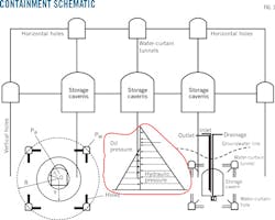
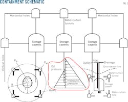
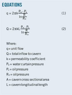
Despite the vicinity of water bearing zones, fractured rock's variable hydraulic continuity often requires use close to the storage caverns of a water-curtain system. The groundwater pressure around the storage caverns should be higher than the pressure of stored oil to prevent oil leakage into the rock mass. Water curtains artificially recharge water in the rock mass to enhance flow patterns and maintain a high hydraulic potential near the storage cavern (Fig. 1). Equations 1 and 2 calculate this flow (see accompanying box).
Site description
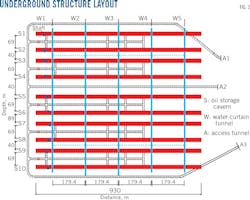
The underground site consists of storage caverns, access tunnels, and water curtain tunnels (Fig. 2). The 10 storage caverns measure 30 m high, 940 m long and 20 m wide, are parallel, and designed to operate as five groups A (1, 2), B (3, 4), C (5, 6), D (7, 8), and E (9, 10). Each group stores crude from a particular source.
A water-curtain system consists of a series of parallel drill holes controlling oil leakage, and water-curtain tunnels. Water-curtain tunnels are 5 m wide, 4.5 m high, and 785-830 m long, with a floor level 25 m above the storage caverns. Five water-curtains stretch across the 10 caverns. Horizontal water-curtain holes are on both walls of each water curtain tunnel at 10-m intervals. Water-curtain system construction took place before storage cavern excavation.
Rock at the pilot site consisted primarily of Proterozoic and Cretaceous granite. Other minor rock types (less than 10% of the overall rock mass) include quartzite and dolerite. Rock-mass classification used the Q-system, with more than 80% of Q-values corresponding to rock of fair-to-very good mass quality. Unweathered rock generally provides excellent mass conditions for cavern construction.
Field-test data and adjacent faults suggested development of three preferred planes 210°-225°<76°, 300°-325°<30-79° and 30°, 83°<39°, 79°, though there wasn't a fault in the study area. Testing during exploration drilling found most of the rocks to be microweathered granites with closed-joint fissures. The tunnel face was wet and highly self-stabilized, without chipping in close-jointed areas.
The storage site featured a subtropical monsoon climate with an annual average temperature of 21.3-21.8° C. Groundwater is present as both pore water and fracture water, with average precipitation of 2,000-2,700 mm/year.
TEM soundings
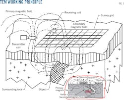
TEM soundings use a receiver and transmitter unit attached to a receiver coil and larger transmitter loop, respectively. The transmitter passes a constant current through the loop, which produces a primary magnetic field. Quickly turning the current off interrupts the primary magnetic field, but to satisfy Faraday's law, currents induced in the ground instantaneously maintain the primary magnetic field.
This current, which flows in closed paths below the transmitter loop, produces a secondary magnetic field. Changes in the secondary magnetic field over time induce a voltage in the receiver coil at the center of the transmitter loop. Because the magnitude and distribution of current intensity depend on the ground's resistivity, the secondary field's voltage provides information regarding this resistivity.
Turning the current off abruptly changes the primary magnetic field and induces an electromotive force in the conducting surroundings. In the ground, this electrical field will result in a secondary current which again results in a magnetic field, the secondary field. Just after the transmitter is switched off, the secondary magnetic field from the current in the ground will be equivalent to the primary magnetic field (which is no longer there).
The resistance in the ground gradually weakens the current (converted to heat) and the current-density maximum moves outwards and downwards, leaving the current density still weaker. The decaying secondary magnetic field is vertical in the middle of the loop, providing the ground consists of planar parallel layers. The decay induces an electromotive force in the coil, measured as a function of time.
Immediately after turning the current in the loop off, the current in the ground remains close to the surface and the measured signal reflects primarily the resistivity of the top layers. At decay continues, the current diffuses deeper into the ground, and the measured signal provides information about resistivity of the deeper layers. The current in the coil measures resistivity as a function of depth (Fig. 3).
System specification
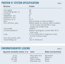
Table 1 summarizes this project's TEM system. Protem 47 from Geonics Ltd is a standard, single-site, ground-based system. The protem divides the transient into time windows then changes the voltage in each window to a digital value. The measuring current source is a 40 × 40-sq m loop, with the receiver coil at the center of the loop measuring the field's vertical component. Measurements are split into three segments, each with 30 time channels (gates) distributed 10/decade.
When used as part of a Protem 47 system for profiling, the TEM47 supplies 2.5 amp to an 8-turn, 5 × 5-m moving transmitter loop to provide a 500-amp/sq m (1.8 amp, 2 × 2 m in this project) dipole moment. With a 25-hz base frequency and 20 gates from 49 μsec to 2.9 ms, this configuration is optimal for horizontal loop surveys of groundwater exploration in bedrock fractures. Electrical sounding occurs simultaneously with the search for fault or dike-like targets.
Detection scheme
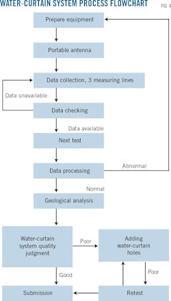
This project takes advantage of transient electromagnetic instruments' high sensitivity to low-resistance (water-bearing) bodies to detect the quality of water curtain in oil storage construction. Fig. 4 outlines the detailed process, which includes the following steps:
• Disturbance source inspection, obstacle clean up (water, vehicle, large metallic objects, etc.).
• Measuring line, test instrument arrangement on the basis of relative locations among water curtain holes, water curtain tunnels, and oil storage caverns.
• Signal collection.
• Test data processing, analysis.
• Water pressure adjustment, water curtain holes addition. Retest to ensure water-curtain system quality.
Focusing on project characteristics and overall arrangement, our field investigation centered on three parts:
• Horizontal water-curtain hole quality.
• Fracture-water detection below water curtain caverns.
• Water exploration in the fracture zone.
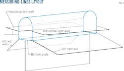
Fig. 5 shows the layout of three measure lines (horizontal, vertical, and inclined) in the left and right walls and bottom plates of the No. 1-5 water curtain tunnels.
Quality tests
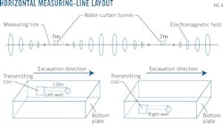
Horizontal measure points lay every 10 m along both walls of No. 1-5 water curtain tunnels, placed between two adjacent water curtain holes to detect the quality of the horizontal water curtain system both before and after water-fillings and before and after hole completion. The space between two adjacent water curtain tunnels was 177.4 m, with a 100-120-m TEM test depth, allowing for perfect coverage of the entire horizontal water-curtain region and prevention of oil leaks (Fig. 6).
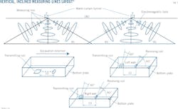
Every 10 m along each tunnel's cavity floor, measure points set left, right, and downward between two adjacent water curtains detected fissure water flow during excavation and after water-filling. The test region covered the entire cavern, improving the ability to supplement water supplies needed to meet construction requirements ( Fig. 7).
Cracks and fractured zones are the key detection region during excavation of storage caverns after filling the water curtain system. Tested water-bearing fracture zones and flow direction can provide the basis for comprehensive water control.
Map setting, analysis
Proprietary WPTEM software analyzed collected TEM data, generating apparent resistivity contour maps in Surfer 8.0. Table 2 helps read the resistivity feature images. Abundant means water outflow from a single well > 11.57 l/sec, medium = 1.16-11.57 l/sec, and weak < 1.16 l/sec. The apparent resistivity of different materials detected by an initial setting line measured in good field-testing condition established the basis for resistivity criteria.
W4 excavation
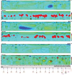
Water Curtain Tunnel 4's water-seal effectiveness investigation focused on the foot of both walls (with 60° to bottom plate) and right below the bottom, after it was filled with water (Fig. 8).
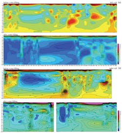
• Bottom plate. Most regions were in medium water status before excavation, full of abundant water at 15-20 m depth. After excavation this region (15-20 m) lost water. A red water-free region at 25-50 m depth, coincided with the storage caverns and access tunnels' location. Weak watery regions increased below 45 m, indicating underground water had been running off during excavation.
• Left wall, 60°. There was no obvious difference before and after excavation, the whole region remaining in a medium watery state; except the 45-70 m region, which coincided with the location of the storage caverns and access tunnels.
• Right wall, 60°. Excavation made no significant difference, the whole region remaining in a medium-watery state with few scattered weak-watery fractured zones; except the 45-70 m region, which coincided with the location of the storage caverns and access tunnels. This included the expected abundant-watery region between 50-80 m where fractures were well developed.
Storage caverns and access tunnels are easily recognized on the map after excavation. Excavation also produced a broken rock zone and the vibration of blasting disturbed joint structures, causing underground water loss. Construction proposals that can be derived from these findings include: grouting and water-blocking should occur promptly after excavation of S7, S8, S9, and S10, because water-head height decreased greatly; and more water-curtain holes should be added to improve connectivity, scattered high-resistance zones demonstrating poor natural connectivity.
W5 excavation
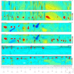
Water Curtain Tunnel 5's water-seal effectiveness investigation focused on the foot of both walls (with 60° to bottom plate) and right below the bottom, after it was filled with water (Fig. 9).
• Bottom plate. Most regions were in abundant-water status before excavation. After excavation the 15-20 m region lost water. A red water-free region at 25-50 m, coincided with the storage caverns and access tunnels' location. Weak watery regions increased below 45 m, especially between 460 and 540 m depth, indicating underground water had been running off during excavation.
• Left wall, 60°. There was no obvious difference before and after excavation, the whole region remaining in a medium watery state; except the 45-70 m region, which coincided with the location of the storage caverns and access tunnels.
• Right wall, 60°. Excavation made no significant difference, the whole region remaining in a medium-watery state with few scattered weak-watery fractured zones at 10-40 m, where fractures were well developed. This excluded the 40-70 m region, which coincided with the location of the storage caverns and access tunnels.
Storage caverns and access tunnels are easily recognized on the map after excavation. Excavation also produced a broken rock zone and the vibration of blasting disturbed joint structures, causing underground water loss. Construction proposals that can be derived from these findings are the same as those for W4.
Though S1-S6 excavation occurred before detection, storage caverns and access tunnels are easily recognizable on the map after excavation. Excavation also produced a broken rock zone and the vibration of blasting disturbed joint structures, causing underground water loss. Both-wall (520-780 m), left-wall (370~380, 420~430, 460~470 m), and right-wall (200-260,450-470 m) regions all need to add water-curtain holes to improve connectivity because rock integrity in this region was too good to transfer water.
W5 seal effectiveness
Horizontal water-seal effectiveness investigation occurred on both walls of the water-curtain tunnels before and after water-filling and before and after water-curtain holes were finished completely in W5 (Fig. 10).
• Left wall. Before water-filling most regions were in medium-watery state (50Ω·m-10Ω·m) and a few were less than 10Ω·m. Water-free regions as thick as 30 m lay between 320-590 m and 640-780 m, but even here scattered parts indicated an abundance of water (> 50Ω·m). After water-filling, the whole region was medium-watery, with abundant-watery parts of 35-80 m between 320-380 m and 465-670 m.
• Right wall. Before water-filling, free parts of 10-15 m, 20-60 m, 40-100m, and 50-80m existed between 360-410 m, 580-600 m, and 725-750 m. Cyclic weak-watery belts lay around these parts, with abundant watery status in 30-60 m between 420-540 m. After water-filling, the whole region was in medium-watery state, previous water-free regions were filled with water, and previous abundant-watery parts dispersed by drill-hole penetration.
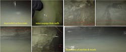
After water-filling, the horizontal water-curtain system had remarkable effects and could reach a medium-watery state at a range of 100 m. A few yellow parts also needed to add holes. The region as a whole was in good test condition even though impounded surface water, water seepage from walls, and pipeline and metal disturbances, created some measurement environments in which mapping discontinuity occurred (Fig. 11).
Acknowledgment
The authors thank China Railway Ergu Group Corp. and China Scholarship Council for their sponsorships of this project and the consultants and engineers contacted, especially Jinzhou project department of China Railway Erju Second Engineering Co. Ltd., for providing their data.
Biblography
Cui, J.H., "A method of analysis on quantity of stored high-pressure gas," Oil and Gas Storage and Transportation, Vol. 9, No. 4, April 1990, pp. 19-26 (in Chinese).
Eric, A., François, C., and Anne., M., "Groundwater management during the construction of underground hydrocarbon storage in rock caverns," International Mine Water Congress, Oviedo, Spain, Sept. 5-7, 2005.
Fitterman, D.V. and Stewart, M.T., "Transient electromagnetic sounding for groundwater," Geophysics, Vol. 51, No. 4, April 1986, pp. 995-1005.
Hoekstra, P. and Blohm, M.W., "Case histories of time-domain electromagnetic soundings in environmental geophysics," Ward, S.H. (Ed.), Geotechnical and Environmental Geophysics, Vol. 2., Society of Exploration Geophysicists, Tulsa, 1990, pp. 1-15.
Li, S., Wang, Z.C., and Ping, Y., "Discrete element analysis of hydromechanical behaviour of a pilot underground crude oil storage facility in granite in China," Tunnelling and Underground Space Technology, Vol. 40, No. 2, February 2014, pp. 75-84.
Meju, M.A., Fontes, S.L., Oliveira, M.F.B., Lima, J.P.R., Ulugergerli, E.U., and Carrasquilla, A.A., "Regional aquifer mapping using combined VES-TEM-AMT/EMAP methods in the semiarid eastern margin of Parnaiba Basin, Brazil," Geophysics, Vol. 64, No. 2, February 1999, pp. 337- 356.
Mills, T., Hoekstra, P., Blohm, M., and Evans, L., "Time domain electromagnetic soundings for mapping sea-water intrusion in Monterey County, California," Ground Water, Vol. 26, No. 6, November 1988, pp. 771-782.
Rehbinder, G., Karlsson, R., and Dahlkild, A., "A study of a water curtain around a gas store in rock," Applied Scientific Research, Vol. 45, No. 2, June 1988, pp. 107-127.
Sandberg, S.K. and Hall, D.W., "Geophysical investigation of an unconsolidated coastal plain aquifer system and the underlying bedrock geology in central New Jersey," Ward, S.H. (Ed.), Geotechnical and Environmental Geophysics, Vol. 2., Society of Exploration Geophysicists, Tulsa, 1990,, pp. 311-320.
Wang, Z.C. and Li, S.C., "Design of water curtain system for an underground oil storage caverns in China. Transit Development in Rock Mechanics," Cai, Y. and Cai, W. (Eds). Taylor & Francis Group, London, 2015.
The authors
Fang Lin ([email protected]) is a PhD candidate in MOE Key Laboratory of Transportation Tunnel Engineering at Southwest Jiaotong University, Chengdu (since 2013). She's also a joint PhD candidate in the school of civil, environmental, and mining engineering at the University of Western Australia, Perth (since 2014). She earned an MS (2013) in architecture and civil engineering, specializing in transportation tunnel engineering, from Southwest Jiatong University.
Hebing Luan ([email protected]) is another a joint PhD candidate in the school of civil, environmental, and mining engineering at the University of Western Australia (since 2013), also pursuing a PhD in resources and safety engineering at China University of Mining and Technology, Beijing (since 2011).
Guowei Ma ([email protected]) is a professor at the school of civil, environmental, and mining engineering at the University of Western Australia. He earned a PhD (2000) in civil engineering at Nan Yang Technological University, Singapore, and a masters of engineering (1992) in civil engineering at Xi'an Jiaotong University, Xi'an, China.
Shougen Chen ([email protected]) is a professor at the Ministry of Education's key laboratory of transportation tunnel engineering, Southwest Jiatong University, Chengdu. He earned a PhD (1999) in civil engineering from Nan Yang Technological University and an MS in tunnel engineering from Southwest Jiatong University.
