Saudi tight gas plays benefit from MSF
Mohammed A. Al-Ghazal
Saad M. Al-Driweesh
Fadel A. Al-Ghurairi
Saudi Aramco
| Based on a paper presented to the SPE Annual Technical Symposium and Exhibition, Al-Khobar, Saudi Arabia, May 19-22, 2013. |
In 2007, Saudi Aramco installed the first openhole, multistage fracturing (MSF) completion systems in Saudi Arabia's deep, highly deviated gas wells (OGJ, June 11, 2011, p. 66). We chose MSF to maximize reservoir contact, completely cover the production interval, and ensure precise treatment fluid placement.1 2
Today, about 50 MSF completions support gas-development in the Southern Area of Saudi Arabia covering both the carbonate Khuff and the sandstone pre-Khuff reservoirs. Results have varied, but MSF wells have generally met or exceeded expectations.3-7
Three MSF technologies were deployed in collaboration with three suppliers. The differences were mainly in the design of the isolation packers, the external pressure sleeves, and the seat and ball materials.3 8
Khuff gas reservoirs are very deep, extremely hot, and highly heterogeneous, and they are developed with complex well trajectories. These conditions create many problems when MSF technologies are being applied, including mechanical and differential sticking as well as hydraulic communication between stages in carbonate formations. This communication prevents creation of separate fractures in each stage of the completion assembly.
This article addresses how these problems were overcome to realize the full benefits of MSF technologies in Saudi Arabia. The article also reviews the production results for MSF test wells and compares them with offset wells that have been completed with other techniques, such as horizontal, open hole, or cased hole.
Mechanical sticking
Some early MSF technology encountered mechanical sticking due to restrictions in the wellbore, especially in cases in which the reamer did not accurately mirror the openhole packer.
To prevent this, a specialty reamer was used to clean out the wellbore before the MSF system was run. The specialty reamer mirrored both the size of the openhole packer (to ensure good cleaning) and the stiffness (to ensure passage through the dogleg).
A detailed drag-modeling program simulated the drag forces imposed while the MSF technology was run downhole. As MSF well candidates are identified, the drag model is run with the planned well-directional survey to evaluate the potential of running the MSF technologies to the target depth. Any necessary changes in the directional plan derive from the modeling results.
Another round of modeling using the actual survey data verifies if the MSF system can be run to the target depth and optimizes the deployment-string design. While it is true that longer packers offer higher differential pressure (given that other features of the packer stay the same), the packer should be short enough to minimize contact with the wellbore and pass any dogleg during the deployment. This makes reaching the target depth easier.
Differential sticking
Some of the early MSF technology also encountered differential sticking because of excessively heavy drilling mud as well as the large pressure differential between two adjacent formations. For example, the Khuff-C formation has six zones with different formation pressures, an environment that is prone to cause differential sticking.
To combat this, we used a fluted centralizer, which enabled positive standoff from the wellbore and prevented hydraulic lock. The centralizer was slip-on with a large water course and swivel device to allow liner rotation. This minimized the contact between the wellbore and the MSF technology, while it maintained a good passage for fluids in the wellbore.
For wells drilled in the minimum horizontal in situ stress plane (σmin), a 1D mechanical earth model (MEM) anticipated formation pore pressure and provided the optimum mud weight. The MEM initially was built with the logging-while-drilling (LWD) composite log and core data from offset wells. The model was then tested on offset wells for verification and calibration.
The MEM is also calibrated during drilling in real time with pressure data from LWD measurements. We employed a 1D MEM as opposed to a 3D MEM because it fits the purpose, requires less input, and is cheaper.
With the optimum drilling mud weight, the model also provides mud weights at which formation breakout, kick, mud loss, and breakdown are might occur. Use of the MEM eliminates any differential sticking by safely lowering mud weight.
Hydraulic communication
We did not see clear fracture signatures in subsequent fracture stages for some Khuff carbonate wells drilled and completed in the maximum horizontal in situ stress plane (σmax).9 This was caused by hydraulic communication between the fracture stages due to natural fractures or by the failure of the isolation packer to keep the pressure and fluid contained in the stage. A much shorter fracture was the result.
We reduced the acid volume and used a balanced system and anchoring tools to address the problem. The acid volume reduction minimized erosion of the rock matrix around the slips of the isolation packer. The balanced system and anchoring tools prevented any excessive movement of the isolation packer during high-pressure fracturing.
Despite these efforts, communication between stages remained. We tried to reduce the communication impact with double packers and by eliminating flowback between stages to avoid the suction effect. However, the communication problem was still unresolved until we changed the wellbore azimuth from the σmax to σmin.
Initially, we had drilled MSF wells toward the σmax for better wellbore stability and a higher rate of penetration (ROP) for the drillbit. However, this resulted in longitudinal fractures that often had some form of hydraulic communication between zones of the first fracture stage and subsequent stages. By changing the wellbore azimuth to the σmin, we created transverse fractures and reduced the communication between completion stages.
The change from σmax to σmin required more planning and time. Before we drilled a well, the geomechanics of the drilling area had to be studied to ensure wellbore stability. Instability can be due to high-horizontal stresses on the wellbore during drilling perpendicular to the natural fractures in the formation.
Also, to improve ROP during drilling in the σmin direction, heavy-duty bits developed for very high revolution/minute applications had to be used.
Test well data
We drilled four test wells in Khuff carbonate and sandstone formations to gauge the effectiveness of MSF technology:
• A carbonate well was drilled in the σmax direction when no communication between stages was observed (Well H-9).
• A carbonate well was drilled in the σmax direction when communication between stages was observed (Well U-1).
• A carbonate well was drilled in the σmin direction when no communication was observed (Well W-1).
• A sandstone well was drilled in the σmin direction when no communication was observed (Well H-1).
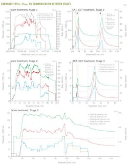
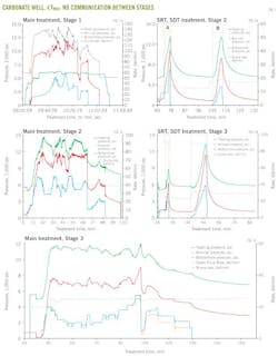
Well H-9 drilled in the carbonate Khuff-C formation toward the σmax direction resulted in longitudinally oriented fractures (i.e., fractures primarily aligned along the wellbore). The well was completed with a three-stage MSF system (Fig. 1).
During fracturing, the first port opened at 5,565 psi after pumping 6 bbl of treated water. The first stage was successfully acid fractured, and the step-rate test and step-down test (SRT, SDT) for the second stage confirmed that there was no communication with the first stage.
The second stage was successfully acid fractured and an SRT, SDT conducted for the third stage also confirmed no communication.
The third stage was successfully acid fractured and, after treatment of the entire interval, the well achieved a stabilized flow rate of 21.1 MMcfd at a flowing wellhead pressure (FWHP) of 2,150 psi.
We didn't perform flowback operations before fracturing any stage, which eliminated suction effects that could lead to hydraulic communication.
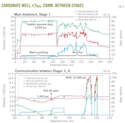
We sidetracked well U-1 highly slanted in the σmax direction with a net reservoir contact of 1,557 ft. We completed the well with MSF technology in the carbonate Khuff-B formation (Fig. 2).
With the MSF deployed at target depth, we opened the first port. The first stage was successfully acid fractured by the pumping of a mixture of pad, acid, and diversion fluid. During the main treatment of the first stage, surface pressure dropped off to 10,800 psi from 16,054.
When we began pumping in Stage 2, there was communication. An immediate pressure decline to 0 psi surface pressure (treating pressure) occurred within seconds after we stopped pumping.
In a new, tight, unstimulated formation, the pressure should bleed off slowly. However, we had flowed back Stage 1 immediately after it was acid fractured. It is likely that the zone was heavily drawn down and there was communication around the packers.
When we drilled in the σmax direction, longitudinal fractures propagated parallel to the borehole and connected the interval stages through the rock matrix. As a result, we matrix acidized Stages 2 and 3. We reached a final, stabilized rate of 18.7 MMcfd, but the full advantage of the MSF system was not realized because matrix acidization isn't as effective as acid fracturing.
By drilling in the σmin direction, we isolated stages by promoting transverse fractures and minimizing longitudinal fractures.
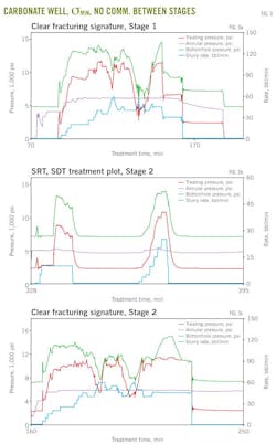
In the carbonate Khuff-B formation, we drilled test well W-1 in the σmin direction and completed it with a two-stage MSF system placed along 1,477 ft of the horizontal lateral. We used MEM in real time to optimize the drilling operation along the σmin (perpendicular to the formation's natural fractures; Fig. 3).
During fracturing, the pressure signatures indicated that separate fractures had been created in each stage. The well is producing at a rate of 35 MMcfd at 3,000 psi FWHP.
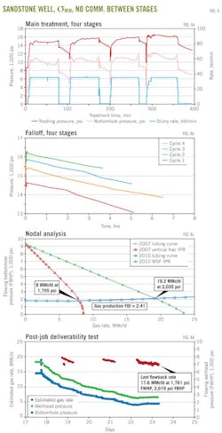
In the Unayzah-A formation, we sidetracked test well H-1, placing a 2,200-ft lateral drilled in the σmin direction, and completed it with a four-stage MSF assembly (Fig. 4). After the completion was set at target depth, the four stages were independently proppant fractured with a total of about 680,000 lb of proppant pumped in the four stages. We used 3D microseismic imaging (fracture mapping) to observe multiple fractures along the openhole lateral with no communication between stages.
CT ball seat milling
MSF technology should be interventionless, but we made coiled tubing (CT) interventions in four MSF wells to mill out ball seats, clean up debris, and open the frac port (if the port did not open after several attempts without milling).8 10 11 We found that it is best to consider both the ball seat material and the CT bottomhole assembly when creating these interventions. The ball seat should be readily millable, and the milling tool should be aggressive enough to drill through the ball seat without damaging the MSF completion.
We also found that weight-on-bit (WOB) is a critical parameter in ball seat milling-out jobs. A CT force simulation should be run to ensure that sufficient WOB is applied. We found the optimum WOB to be 800-1,000 lb. If too little weight is applied, there will be no progress; if too much is applied, the mill may stall.
MSF well production
The production from our MSF completed wells has exceeded expectations. Production in two test fields (Field A, Field B) was greater that wells completed with other techniques, such as horizontal open hole and cased hole, in terms of stabilized gas production rate. In Field A, MSF wells produce at a rate about three times the rate of non-MSF wells. In Field-B, MSF wells produce at a rate about 2.3 times that of non-MSF wells.
While it is true that the reservoir properties are different from well to well in both fields and that most of the non-MSF wells are older, we believe that using MSF technologies is a competitive advantage.
We made the following observations that may be useful in deciding to use MSF technology:
• Strategic mitigation practices have practically eliminated deployment problems associated with MSF and have resulted in consistently successful deployment of the technologies to their target depth.
• Proper use of MEM has improved wellbore stability by providing the optimum mud weight during drilling in the σmin direction.
• Multiple transverse fractures maximize the contact area between the well and the formation.
• Carbonate wells drilled in the σmax direction with longitudinal fractures produced well, but those drilled in the σmin direction created multiple transverse fractures with MSF and a higher production rate.
• Changing the horizontal wellbore drilling direction to σmin from the σmax minimized hydraulic communication between the fracture stages in carbonate formations.
• A balanced system and anchoring tools prevent excessive movement of the isolation packers during high-pressure fracturing.
• The millability of the MSF system should be evaluated if it seems likely that CT ball seat milling-out will be required during the life of the well.
References
1. Al-Ghazal, M.A., Al-Ghurairi, F.A., and Al-Zaid, M.R, "Overview of Open Hole Multistage Fracturing in the Southern Area Gas Fields: Application and Outcomes," Saudi Aramco Ghawar Gas Production Engineering Division internal documentation, March 2013.
2. Al-Ghazal, M.A., and Abel, J.T, "Stimulation Technologies in the Southern Area Gas Fields: A Step Forward in Production Enhancement," Saudi Aramco Gas Production Engineering Division internal documentation, October 2012.
3. Al-Ghazal, M.A., Al-Sagr, A.M., and Al-Driweesh, S.M, "Evaluation of Multistage Fracturing Completion Technologies as Deployed in the Southern Area Gas Fields of Saudi Arabia," Saudi Aramco Journal of Technology, Fall 2011, pp. 34-41.
4. Al-Jubran, H.H., Wilson, S., and Johnston, B, "Successful Deployment of Multistage Fracturing Systems in Multilayered Tight Gas Carbonate Formations in Saudi Arabia," SPE Deep Gas Conference and Exhibition, Manama, Bahrain, Jan. 24-26, 2010.
5. Hamid, A.H., Kalil, M.E., Al-Mohammad, A.K., Al-Khamees, S.A., El-Mofty, W., Johnston, B., et al. "Successful Drilling and Deployment of an Open Hole Multistage Fracturing System in a Deep and Hostile Sandstone Gas Reservoir," SPE, DGS Saudi Arabia Section Technical Symposium and Exhibition, Al-Khobar, Saudi Arabia, May 15-18, 2011.
6. Rahim, Z., Al-Kanaan, A.A., Johnston, B., Wilson, S., Al-Anazi, H., and Kalinin, D, "Success Criteria for Multistage Fracturing of Tight Gas in Saudi Arabia," SPE, DGS Saudi Arabia Section Technical Symposium and Exhibition, Al-Khobar, Saudi Arabia, May 15-18, 2011.
7. Solares, J.R., Giraldo, C.A., Al-Marri, H., Al-Hussain, H., Abualhamayel, N., Ramanathan, V., et al., "Successful Multistage Horizontal Well Fracturing in the Deep Gas Reservoirs of Saudi Arabia: Field Testing of a Promising, Innovative, New Completion Technology," SPE Annual Technical Conference and Exhibition, Denver, Sept. 21-24, 2008.
8. Al-Ghazal, M.A., Abel, J.T., Wilson, S., Wortman, S., and Johnston, B., "Coiled Tubing Operational Guidelines in Conjunction with Multistage Fracturing Completions in the Tight Gas Fields of Saudi Arabia," SPE Middle East Unconventional Gas Conference and Exhibition, Abu Dhabi, Jan. 23-25, 2012.
9. Rahim, Z., Al-Kanaan, A.A., Al-Anazi, H., Al-Harbi, A., Ginest, N., Halim, A., et al., "Integration of Drilling, Completion, and Stimulation Technology Boosts Saudi Arabian Gas Well Performance," SPE International Petroleum Conference and Exhibition, Abu Dhabi, Nov. 11-14, 2012.
10. Al-Ghazal, M.A., Abel, J.T., Al-Buali, M.H., Al-Ruwaished, A., Al-Saqr, A., Al-Driweesh, S.M., et al., "Coiled Tubing Best Practices in Conjunction with Multistage Completions in the Tight Gas Fields of Saudi Arabia," SPE Saudi Arabia Section Technical Symposium and Exhibition, Al-Khobar, Saudi Arabia, Apr. 8-11, 2012.
11. Al-Ghazal, M.A., Al-Driweesh, S.M., Al-Ghurairi, F.A., Al-Sagr, A., and Al-Zaid, M., "Assessment of Multistage Fracturing Technologies as Deployed in the Tight Gas Fields of Saudi Arabia," International Petroleum Technology Conference, Beijing, Mar. 26-28, 2013.
The authors
Mohammed A. Al-Ghazal ([email protected]) is a production engineer for Saudi Aramco. He holds a BS in petroleum engineering from King Fahd University of Petroleum and Minerals (KFUPM), Dhahran and is pursuing his MS at the University of Southern California, Los Angeles. Al-Ghazal is a member of the Society of Petroleum Engineers.
Saad M. Al-Driweesh ([email protected]) is a general supervisor in the Southern Area production engineering department for Saudi Aramco. He is involved in gas production engineering, well completion, and fracturing and stimulation. Al-Driweesh received his BS in petroleum engineering from KFUPM and is a member of SPE.
Fadel A. Al-Ghurairi ([email protected]) is a petroleum engineering consultant and technical support supervisor. He has 24 of years of experience in production and reservoir engineering. Al-Ghurairi holds a BS in petroleum engineering from KFUPM.
