Energy optimization drives design for Saudi Aramco NGL-recovery plant
Maan Mohammed Iskander
Saudi Aramco
Dhahran
| Based on a presentation to the 2013 GPA Europe Annual Conference, Edinburgh, Sept. 18-20. |
Designing a grassroots NGL-recovery plant in the empty quarter of Saudi Arabia required formulation of energy optimization initiatives because the area is remote and electrically isolated from any nearby network and water is scarce.
Four initiatives conceived during the project's frontend engineering and design (FEED) phase resulted in cost savings and power and energy savings of more than 27,500 hp.
Because the Shaybah NGL-recovery plant is nearing completion for start-up this year, the initiatives have yet to be tested. All the initiatives were thoroughly reviewed and approved by the FEED contractor's consultants in addition to Saudi Aramco's central engineering. Some of the initiatives are in fact not new in the oil and gas industry, having been implemented worldwide for several years with no concern.
The Shaybah NGL-recovery plant, part of Saudi Aramco's NGL program, will support its corporate strategy for maximizing revenues by installing grassroots NGL recovery at Shaybah field in the Empty Quarter of the Arabian Peninsula southeast of Saudi Arabia near to the border with the United Arab Emirates.
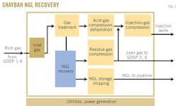
The plant will extract NGLs from 2.4 bcfd of Shaybah associated gas arriving from different gas-oil separation plants (GOSPs) and deliver the lean gas at the required pressure from the Shaybah NGL-recovery plant to GOSP–2 and GOSP–4 through interconnecting pipelines where the gas will be reinjected.
NGL will be sent through pipeline to other Saudi Aramco downstream facilities for fractionation.
The Shaybah NGL-recovery plant consists of the following main process areas:
- Inlet area
- Gas sweetening
- NGL recovery
- Flare and burn pits
- Acid-gas dehydration and compression
- Residue-gas compression
- Injection-gas compression
- Refrigerant make-up
- NGL storage and shipping
- Power generation and utilities
FEED for Shaybah NGL recovery began in 2009. During this stage, an energy optimization study was conducted to capitalize on potential process and energy optimization initiatives raised by the project team. The purpose of the study is to maximize heat recovery within the process through use of existing equipment to maximize energy efficiency and build a cost effective fit-for-purpose plant.
The study addresses the requirements of Saudi Aramco engineering procedures that stipulate that projects shall be optimized for the efficient use of thermal and electrical energy when the combined fuel consumption of the process units exceeds 100 million btu/hr (equivalent to 2.2 MMscfd fuel gas @ high heating value (HHV) = 1,080 btu/std. cu ft).
In the case of Shaybah NGL, the electrical energy demand was estimated at 370 Mw ~ 1,260 million btu/hr and the process thermal demand was estimated at about 700 million btu/hr.
In addition, several factors unique to Shaybah NGL recovery made this energy optimization study an objective to pursue. These factors include:
• The extreme remoteness of the Shaybah area and its isolation from any electrical network.
• Scarce ground water and, when available, it is high in salinity and total dissolved solids (TDS).
• Harsh environment and logistical difficulties.
The process and energy optimization initiatives resulted in energy savings, lower capital expenditures (capex), and lower operating and maintenance costs.
Acid-gas dehydration
The originally specified design for acid-gas compression and dehydration followed the design basis scoping paper (DBSP). Acid gas from the amine strippers in addition to the flash gas from rich amine flash drum were to be compressed by multi-stage acid-gas compressors to 1,450 psia. The acid gas was to be dehydrated at the final stage of the compressor with two redundant trains of triethylene glycol (TEG) dehydration units to meet an acid-gas water dewpoint of 35° F.
Dry gas from the overhead of the TEG contactor is comingled with the compressed residual gas before injection downhole. Acid-gas dehydration is essential for eliminating the possibility of water condensing from the gas especially in winter, which could lead to corrosion of the pipeline or the injection-well casing.
Saudi Aramco further specified that the DBSP specification was meant to meet the minimum acid-gas water dewpoint of 35° F. at 1,450 psia. As the design progressed, the contractor proposed to relocate the TEG dehydration units at an interstage pressure of the acid-gas compressors.
The reason for the relocation was that, at the 1,460-psig design discharge pressure of the acid-gas compressors, the acid gas was in the super critical zone of the phase envelope and TEG dehydration designs in this region are not well established. Subsequently, the TEG dehydration units were moved to the compressor third interstage around 500 psia.
Using a model specifically designed for phase equilibrium involving water, acid gas, and sweet and sour natural gas, calculations determined the water content curves for the three possible acid-gas compositions at various operating pressures. Table 1 shows the water content corresponding to a water dewpoint of 35° F. at 1,450 psia, the water's dewpoint temperature corresponding to the same water content at 500 psia, and the hydrates' formation temperature at 500 psia were determined.
Table 1 also shows that the required water content becomes more stringent as the hydrocarbon content in the acid gas increases. For example, in the worst case, water content of 32.3 lb/MMscf would need to be achieved in order to satisfy the specified 35° F. dewpoint at 1,450 psia. A TEG dehydration unit would be able to meet the required water content specified in the DBSP.
Water-content curves show that the acid-gas water content reduces towards higher pressure within the phase envelope. Hence the optimum location of the TEG package is the third interstage pressure within the phase envelope, which gives reduced dehydration load to the TEG dehydration units.
Table 1 also shows that the DBSP specification cannot be achieved with chilling for the worst-case scenario (AG + FL + FG) because the water dewpoint temperature is well below hydrate-formation temperature.
Later, the water-content specification was even questioned for acid gas. It was agreed that acid-gas dehydration should be designed to achieve a maximum water content of 7 lb/MMscf when comingled with residue gas before injection. This new specification opened the way to evaluation of the most technically and economically feasible process approach to dehydrate the acid gas (e.g., TEG, chilling with a minimum 15° F. approach to hydrate formation temperature) to meet the specified water content.
Chilling vs. TEG dehydration
In order to determine the new required water-content specification in the acid gas that would result in a combined acid/residual gas specification of 7 lb/MMscfd in the mixed acid/residual gas, discussion considered all the possible acid-gas compositions combined with the governing design basis for gas injection forecasts in 2014 and 2018.
As the residual gas water content is nearly 0 lb/MMscf, the water content of the mixed acid/residual gas is mainly a function of acid-gas water content, acid-gas flow, and residual-gas flow. Table 2 shows the forecast gas-injection rates and the corresponding required acid-gas water content to meet a mixed water-content specification of 7 lb/MMscf.
The most stringent water-content requirement is in the 2014 case, corresponding to a water content of 73.2 lb/MMscf for the acid-gas mixture of (AG+FL+FG).
Based on this analysis, the water spec for the acid-gas mixture (AG + FL + FG) was set at 70 lb/MMscf. The corresponding water dewpoint temperature is about 81.5° F. at 500 psia. Table 3 shows the water content for all the acid-gas mixtures corresponding to a water dewpoint of 81.5° F. at 500 psia and the corresponding hydrate-formation temperatures.
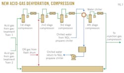
The revised dewpoint specification can be met easily by TEG dehydration. It was more economical, however, to install acid-gas chillers instead of complete TEG dehydration. The acid-gas chiller will be located at the discharge of the third-stage acid gas compressor.
The chiller would cool the acid gas to 81.5° F., which is at least 17.5° F. higher than the hydrate-formation temperature for any expected mixture of acid gas to achieve the required water content of 70 lb/MMscf.
The new acid-gas dehydration configuration (Fig. 2) consists of the acid-gas chiller in which the acid gas will be cooled by chilled water. Liquid propane at 137 psia from the second stage of the propane refrigeration loop chills the water in a dedicated propane chiller. While it is possible to chill the acid gas directly with a propane chiller, using a dedicated closed chilled-water system will ensure that any leak of acid gas doesn't affect the propane refrigeration system. The system will also be designed with temperature control to ensure the water temperature remains higher than the hydrate formation temperature of the acid gas.
Propane required for the water chillers will be supplied from both NGL-recovery propane refrigeration systems (primary, backup). The total propane required for the water chiller is less than 5 MMscfd, corresponding to a marginal increase in the propane refrigeration load of less than 1.5%/NGL train.
This simplified new acid-gas chilling process eliminates the need for two 100% complete TEG dehydration systems (contactor, flash drum, stripper, reboilers, fin fans, heat exchangers, TEG storage, etc.) and reduces acid-gas compressor's power and aftercooler's duty.
These savings exclude the reduced operational and maintenance costs associated with a TEG system and the reduced plot space of acid-gas dehydration. Furthermore, the simplified process eliminated the operational risks and training requirements associated with operating an acid-gas (20% H2S) TEG system.
Deleting feed, heat exchanger
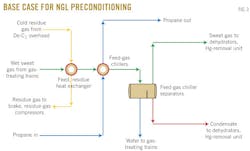
Wet (water-saturated) sweet gas from the gas-treating trains combines in a common manifold and the flow splits to the two NGL-recovery trains under flow ratio control. The wet sweet gas passes through a feed and residue heat exchanger (2 x 50%) to lower the gas temperature. The brazed aluminum heat exchanger (BAHE) uses a cold stream from the overhead of the demethanizer column to cool the wet sweet gas.
The gas is further cooled to 67° F. in feed-gas chillers that use propane as a refrigerant media. The intent of the feed-residue heat exchanger is to use the low temperature of the residue gas to cool the feed gas and hence reduce the load on the feed-gas chiller.
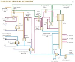
The two-phase (cooled gas and liquid) feed is then routed to the feed-gas chiller separators where the condensed water and hydrocarbon liquid are separated. Both the gas and condensate will be dehydrated and mercury removed before the gas and condensate are processed in the cryogenic section of the NGL-recovery unit (Fig. 3).
Power optimization
As seen in Fig. 3, the residue gas from the overhead of the demethanizer column flows to the feed-residue heat exchanger before entering the brake compressor and residue-gas compressors. The base case considered for the residue-gas compressors is a 4 x 25% configuration, which has an estimated motor rating of 45,000 kw/train (60,346 hp). Each train has low pressure (LP) and high pressure (HP) process stages. The original intent was to have these large compressors operated direct online (DOL) and avoid the need for motor water cooling.
The preference to optimize the residue-gas compressors' scope and maintain the motor rating to remain air-cooled has allowed of this objective to be considered. It was later envisioned that deleting the feed-residue heat exchanger will reduce the power requirement of the residue-gas compressors.
Following the deletion, the suction temperature to the residue-gas compressor will drop to 72° F. from 115° F. because the cold residue-gas stream will not exchange with the warm feed gas. The lower suction temperature leads to lower mass flow rate, higher density of the gas, and hence lower compressor power.
Deletion of the feed-residue heat exchanger increases the propane compressor power but at the same time reduces the residue-gas compressors' power. Despite the savings by the heat exchanger's deletion and reduction in the residue-gas compressors' power, the total installed cost (TIC) for the propane compressors increases. The savings on the residue-gas compressor power, however, outweighs the incremental cost of the propane compressors. A total reduction in capital cost is achieved.
Table 4 shows the savings in the compression power after deletion of the feed-residue heat exchanger.
Chiller temperature increase
As highlighted in the previous section, one negative effect of deleting the feed-residue heat exchanger is the increase in propane (refrigeration) load merely for the feed-gas chillers. The outlet feed-gas temperature downstream the feed-gas chiller is 67° F., which is greater than the hydrate-formation temperature of the feed gas.
Another factor for chilling the wet feed gas from the gas-treating trains is to separate the condensed water and hydrocarbon liquid. This separation will help reduce the water content in the feed gas before the adsorption process in the molecular-sieve dehydration unit and hence optimize the size of the dehydrators.
A study assessed the feasibility and practicality of relaxing the feed-gas chiller's outlet temperature and hence reducing the load on the propane compressors. An assessment of the entire NGL-recovery unit, including all critical parameters, revealed that a change to 84° F. from 67° F. is promising (Table 5).
The table makes clear that the propane circulation rate, absorbed power, and demethanizer bottoms reboiler duty reduces if the feed-gas chiller temperature increases to 84° F. from 67° F. Total savings in power and energy are 10,500 hp and 10,900 hp, respectively. Based on vendor data, however, the size of the molecular-sieve dehydrators increase only marginally, which justifies the change. Therefore, the higher temperature of 84° F. was implemented in the NGL-recovery unit's design.
Eliminating de-C1 pumps
The feed stream after filtration, inlet separation, dehydration, and mercury removal will pass to the cryogenic section of the NGL-recovery unit for final separation into two main products (residue gas and NGL). The feed-gas temperature is lowered by three methods of process cooling in addition to mechanical cooling (turboexpander):
1. Gas-gas heat exchangers (BAHE), in which the feed-gas temperature reduces by indirect heat exchange with the cooled residue gas from the demethanizer column's overhead.
2. Chillers or "Core-in-Kettle" (BAHE), in which the feed-gas temperature reduces inside cores fully submerged in liquid cooled propane (refrigeration system).
3. Reboilers (BAHE), in which the feed-gas temperature reduces by indirect heat exchange with the draw-off liquid from the demethanizer column.
The side draws from the demethanizer contribute to minimizing the refrigeration requirement. The base case for the Shaybah NGL-recovery process was to utilize side-draw pumps to transfer the cooled hydrocarbon liquid accumulated at the demethanizer' s chimney trays to their respective reboilers. Three side draws are available for the reboiler duty where each side draw has a set to two pumps (one online and one standby) making it a total of 12 side-draw pumps for the two NGL-recovery trains.
Thermosyphon reboilers
The rule of thumb in any hydrocarbon operation is to reduce rotating equipment as much as possible. The importance of minimizing those machines arises from the fact that they require frequent maintenance to ensure reliable operation in addition to high operational and maintenance costs.
In fact what inspired the team to look for alternatives is the bad history of these pumps in one of Saudi Aramco's NGL-recovery plants. The idea arose to adopt a thermosyphon reboiler concept in lieu of side-draw pumps.
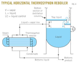
In our situation, a thermosyphon reboiler requires no pumping of liquids from the demethanizer chimney trays into the reboiler. Its function is based on the fluid density difference between the reboiler inlet from the bottom of the chimney train in the column and the reboiler outlet back to the column. The difference in density drives the liquid head required to push the liquid from the column into the reboiler in a natural circulation (Fig. 4).
The alternative option of thermosyphon reboiler seems to be promising but requires further verification from the contractor and the BAHE manufacturer to ensure its feasibility. It was agreed that the manufacturer would engineer and design the liquid head requirements after the first submission of the heat exchanger and vessel drawings. Later, the manufacturer can confirm the liquid head requirements and will make necessary changes to accommodate the hydraulic calculations.
As agreed the thermosyphon static head requirements will be finalized with the lump sum turnkey contractor after a purchase order is issued, using actual piping and equipment layouts and taking into consideration that the manufacturer has included typical allowances for static head and piping losses in its design.
Based on hydraulic analysis and with few adjustments in piping and nozzle sizes and orientation, the idea proved feasible. Eliminating the side-draw pumps (total of 12) around the demethanizer column through use of thermosyphon BAHE resulted also in reducing the demethanizer column height, simplifying the piping network, and reducing plot space, thus resulting in cost savings on TIC (Fig. 5).
Hot oil system
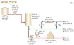
The hot oil system (HOS) provides the required heat loads for Shaybah NGL recovery. Oil is heated by heat-recovery units (HRU) that use the hot exhaust flue gas from the combustion gas turbine generators. The HOS is a closed loop design. A hot oil reservoir is maintained in the 2 x 50% hot-oil expansion tanks. The tanks are designed to contain the volume of hot oil expanded from ambient temperature to its operating temperature between high liquid level and low liquid level.
Pressure is maintained in the tanks by a pressure controller that admits nitrogen on low pressure, or vents nitrogen to a low-pressure flare on high pressure. In the event of low liquid level in the expansion tank, the hot oil make-up pumps route hot oil from the hot oil storage tank to the hot oil circulation loop.
Six centrifugal hot oil circulation pumps (6 x 25%; two are spare) take suction from the hot oil expansion vessels and maintain pressure in the HOS circuit. The hot oil is routed to the hot oil heat-recovery units. A minimum flow controller operates on the outlet line to recycle back to the expansion tanks.
All heat recovery units (HRUs) are unfired heaters. The installed HRUs provide the total plant heat requirement. One spare HRU maintains the required sparing (N+1) for this system. The combustion gas turbines exhaust ducts are provided with bypass stack and isolation damper. The hot oil outlet temperature of 572° F. is controlled by the position of the HRU dampers. Hot oil is then pumped to the users at 572° F., where heat is extracted.
A 1 x 100% trim cooler takes a side stream from the supply line to maintain a constant supply temperature. The trim cooler ensures controllability across the full range of operating conditions of the system. Hot oil returns to the hot oil expansion tanks at a minimum temperature of 266° F. to avoid acid dewpoint corrosion in the hot oil heat-recovery units. The type of hot oil considered is Dowtherm G, an oil suitable for temperatures up to 680° F. (Fig. 6).
A thorough study addressed the following for the Shaybah NGL-recovery HOS:
• Investigate the possibility of using two levels of heating temperature.
• Evaluate the requirement for trim coolers to protect the hot oil system.
Required temperature levels
The total heat load required has been calculated to be 162 Mw. Several areas require heating, the two largest consumers being:
• Gas mole-sieve dehydration unit at 572° F. (about 20% of total duty).
• Amine regeneration unit at 347° F. (about 75% of total duty).
The design basis was to run two separate headers from the HRU to satisfy the temperature required by the two main process users. From economic and operational points of view, it was not cost effective to have these separate headers due to piping's length. The main pipe rack length is around 1.2 km.
Several options were evaluated, including installing direct-fired heater for the gas mole-sieve dehydration. The most optimum and least costly was to run only one header at the highest temperature required—572° F.—and achieve the lower temperature of 347° F. for the amine regeneration unit by the means of a recycle line from the hot oil outlet achieved by recycle pumps.
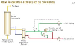
The idea is simply as the follows: Hot oil is the heating medium in the regenerator's reboilers, but as the hot oil main supply temperature is 572° F., which can potentially degrade the amine, cold hot oil return at a temperature of 300° F. from the reboilers outlet is recirculated in the reboilers' hot oil circulation pumps to maintain the hot oil supply temperature at the inlet to the reboilers at 347° F.
The hot oil circulation rate is cascade-controlled by the regenerator overhead temperature and at design conditions it is maintained at 18,500 gpm (Fig. 7).
Trim cooler
During periods of low heating demand, the duty supplied by the HRUs can exceed that required by the users. Hot oil duty is reduced by controlling the louvers on the HRUs; however heat leakage must be handled. Therefore, trim coolers may be installed with temperature control.
Later, it was evaluated that a trim cooler in the hot oil system is needed. The trim cooler is not required to protect the hot oil system against high temperature but ensures controllability across the full range of operating conditions of the system.
Adding a single 8-Mw hot-oil trim cooler costs $194,900 with TIC costs at $409,100. These costs show that the TIC for the trim cooler is not very large in terms of the overall TIC for the hot oil system. Hence, the benefit achieved in enhanced operability outweighs the capital cost of this item.
Table 6 summarizes the overall benefit and optimization in cost and energy requirement (Option 2) implementing the one level of hot oil temperature and the cost associated for the additional equipment.
The author
Maan Mohammed Omar Iskander ([email protected]) is a planning engineer for Saudi Aramco Co. in the facilities planning department based in Dhahran. He joined the company in 2001, working at the Berri gas plant. Iskander holds a chemical engineering degree (2001) from King Fahd University of Petroleum & Minerals, Dhahran, is a certified project management professional, an international member of the Project Management Institute, and a member of the American Society of Safety Engineers, the American Society of Chemical Engineers–Saudi Arabia section, and the European Chapter of the Gas Processors Association.
