Texas gas plant retrofits to improve ethane recovery
Guang Lee Jie Yu Sudhir V. Golikeri
Bechtel Hydrocarbon Technology Solutions Inc.
Houston
Patrick Drew Bonnie Dumas
Pioneer Natural Resources USA Inc.
Dallas
| Based on a presentation to the GPA Annual Convention, San Antonio, Apr. 7-10 |
Pioneer Natural Resources USA Inc., Dallas, in 2012 employed basic process design provided by Bechtel Hydrocarbon Technology Solutions, Houston, to increase ethane recovery at its 80-MMscfd gas plant near Amarillo, Tex., to more than 80% from 40%.
This article describes the evaluation approach including identification of the constraints in the current operation, comparison of different retrofit options, and selection of the best retrofit option with maximum use of existing equipment.
The selected option was to recycle residue gas, improve heat integration by reconfiguration of existing heat exchangers, and redeploy idled equipment. Pioneer completed the necessary modifications in less than 6 months.
Production from newly discovered abundant reserves of shale gas in the US has sharply driven down the price of natural gas, and demand for NGLs has experienced growth as petrochemical feedstock and as a clean fuel for heating and cooking. Consequently, NGLs trade at a premium to natural gas, and NGL recovery becomes a major revenue earner for the natural gas processing business.
This trend is projected to continue.
Pioneer Natural Resources owns the Fain I gas plant near Amarillo, a turbo-expander plant built around 1980. The plant also has a cold box for nitrogen rejection and helium recovery.
In 2011, it was operating at reduced capacity of 50 MMscfd with ethane recovery at 40%. Pioneer wanted to raise ethane recovery to more than 80%.
Retrofit methodology
It is not unusual for a plant that is older than 20 years to operate with feed conditions and throughput very different from its original design, resulting in reduced performance. A good retrofit project requires a creative approach. Proper diagnosis of constraints in the existing process configuration and equipment can uncover the best slate of cost-effective retrofit options for evaluation.
The first step in this project was to set project goals and design basis. These were to:
• Evaluate options to increase ethane recovery to more than 80%.
• Determine effects on the nitrogen rejection unit.
• Use existing plant compression as much as feasible.
• Use existing separators and exchangers as much as feasible.
• Optimize operating parameters to utilize existing equipment fully.
• Minimize fuel use.
• Produce residue gas that meets pipeline quality specifications.
The next step was to assemble the following information:
• Process flow diagrams (PFDs) and piping and instrumentation diagrams (P&IDs).
• Major equipment datasheets.
• Distributed control system (DCS) data dump or screen prints of the 2012 operation.
• Well-tuned simulation model of the 2012 operation.
Having a well-tuned model served as a good starting point to begin proper evaluation of retrofit options.
Retrofit options
Several options were evaluated to increase NGL recovery.
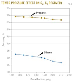
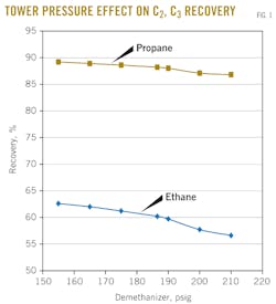
• Option 1–Optimize demethanizer pressure. A pressure sensitivity study examined the effect of changing demethanizer operating pressure on ethane recovery. As shown in Fig. 1, both ethane and propane recoveries improve by reducing the demethanizer operating pressure because relative volatility of most components increases with decreasing pressure.
An increase in relative volatility facilitates the separation. Therefore, a greater separation can be achieved with the same energy input.
A lower tower pressure would also benefit the heat integration of side and bottom reboilers with process cooling, as a lower temperature profile with decreasing tower pressure increases temperature approach. However, it would add load to the residue-gas compressor.
• Option 2—Raise feed pressure. In the 2012 operation, the feed pressure to the NGL section was 680 psig. This option considered increasing the feed pressure to 850 psig by using an existing standby compressor or by installing a new compressor.
A review of the equipment design pressure was needed to confirm that raising pressure was practically feasible. All the major equipment from the NGL section inlet to the expander suction vessel have design pressures of 1,000 psig. The expander outlet vessel has a design pressure of 550 psig. The demethanizer and the stabilizer both have a design pressures of 450 psig.
Therefore, the existing piping and equipment should be able to handle the elevated feed pressure.
Based on process simulation, ethane recovery could increase 17% by an elevation of the NGL section's inlet pressure to 850 psig.
• Option 3–Lower the cold separator's operating temperature. In the 2012 operation, feed gas to the cold separator drum was chilled by propane refrigerant in the propane gas chiller to -23º F. This option considered lowering the feed-gas temperature, leaving the propane gas chiller to -30º F. This can be achieved by reducing the propane refrigerant's pressure on the shell-side of the gas chiller (E-5).
Pioneer was concerned that the propane compressor had experienced liquid carryover from the low-stage suction drum. A further reduction in the low-stage suction pressure may increase the risk of liquid carryover.
Pioneer said, however, that the feed gas leaving the propane gas chiller had been operated successfully at -28º F. Therefore, this option was refined to achieve feed-gas temperature leaving the propane gas chiller to -28º F. by lowering the low-stage propane refrigerant pressure. Ethane recovery would increase by 6.3% in this option.
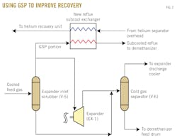
• Option 4–Incorporate gas subcooled process. The gas subcooled process (GSP) consists of taking a portion of cold feed gas from the cold separator (suction drum to turboexpander). It is condensed and further subcooled with refrigeration from cold residue gas leaving the demethanizer.
The subcooled liquid then becomes the reflux to the demethanizer. GSP usually achieves a higher ethane recovery compared with the case in which all the gas from the cold separator flows through the turboexpander.
Fig. 2 shows the simulation with GSP to improve ethane recovery.
Repiping V-5 and V-7 overheads would be required for this option. A new heat exchanger to subcool the reflux was also required. A 4% improvement in NGL recovery could be expected with this retrofit.
Because the turboexpander was already operated in turndown condition, however, taking away a portion of gas to GSP from the turboexpander might worsen the turndown situation and cause the inlet guide vane to close further. Therefore, the marginal recovery improvement would not justify the cost and complexity of new equipment.
• Option 5–Upgrade turboexpander. Based on process simulation of 2012 operation, the turboexpander was estimated to operate at 65% adiabatic efficiency and the associated compressor at 60% efficiency. The low efficiency was largely caused by the turboexpander running at turndown conditions.
Rewheeling the existing turboexpander would allow the turboexpander to operate at 80% adiabatic efficiency and the associated compressor to operate at 70% adiabatic efficiency.
Ethane recovery was estimated to increase by 4% with the turboexpander upgrade. This option had a drawback of high capital cost and long lead time.
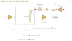
Option 6–Residue-gas recycle as demethanizer reflux. In this option, a portion of residue gas is compressed, condensed, subcooled, and sent as reflux to the demethanizer.
This additional methane-rich reflux from residue-gas recycle provides enhanced rectification of tower vapor so that more ethane and heavier components can be recovered.
The design redeploys one of the prechilling branches for the inlet gas to cool the residue gas and further chill it in a new exchanger.
This option would require additional compressor and gas/gas heat exchanger. Pioneer preferred to reuse an idled compressor, KR-104. Previously, 10 MMscfd of residue gas was compressed by this compressor and sent as sales gas.
Fig. 3 illustrates the addition of residue-gas recycle to demethanizer as reflux. The new route appears as the dashed red line.
Table 1 shows the sensitivity of increasing residue-gas recycle as reflux on the process performance.
With 8.6 MMscfd recycle rate, the ethane and propane recoveries improve to 85% and 99%, respectively. The propane refrigeration load also increased but was within the equipment's capacity.
Two existing idled brazed aluminum heat exchangers (BAHX), EP-313 and EP-314, were identified as candidates for the residue-gas chiller. Eventually EP-313 was determined more appropriate because of the similarity between its original design and the new service. The exchanger was then rerated to confirm its suitability.
Table 2 summarizes the ethane recovery increase and associated equipment and operational changes for each retrofit option. Clearly, Option 6 had the largest ethane recovery increase.
As can be seen, several other options were also identified for potential ethane recovery increase. Pioneer will be able to use this insight to plan further operational improvements.
Implementation
Pioneer chose to Option 6 and decided to purchase new compressors to produce 15 MMscfd of reflux to achieve even higher ethane recovery. The longer lead times for new compressors, however, made it appealing to use the existing residue compressor KR-104 and operate with a lower reflux rate until the new compressors could be installed.
The only other major piece of equipment required was a heat exchanger to condense the reflux to the demethanizer. Pioneer decided to reuse equipment from the idled Fain II gas plant because there is no plan to restart that plant in the near future. Several multipass brazed aluminum exchangers from Fain II were evaluated for this service. A three-pass exchanger that fit the service was relocated and put into its new service.
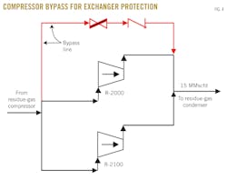
The difficulty with using this brazed aluminum exchanger in its new service was the possibility of drastic temperature changes during operation, especially if the demethanizer reflux compressors shut down. In order to protect this exchanger, a bypass with check valve around the compressor was installed to ensure that there would always be flow to the reflux pass of the exchanger (Fig. 4).
If the compression fails, this feature should protect the exchanger from changing temperature too quickly. A control scheme was installed in the pressure control valve downstream of the new demethanizer reflux compressors. The valve will open if the flow rate to the new reflux condenser falls below a required value, allowing the gas to bypass the exchangers and enter the demethanizer.
Two new electric, motor-driven, 600-hp compressors were chosen for the residue reflux compressors. Electric motors were chosen because of the shorter lead time compared with gas-driven compressors and they help minimize fuel use and because of the availability of purchased power at the plant. The new compressors would compress residue gas from about 380 psig to 1,000 psig.
These compressors were the longest lead item in the project; piping was therefore also installed to use the existing KR-104 in the interim for reflux compression. There would not be 15 MMscfd available for reflux, but the compression would pay for itself while Pioneer waited for the new compression to be installed.
Since the residue gas would reach temperatures well below the freezing point of lubricating oil, it was necessary to install a filter coalescer downstream of the new and existing compressors.
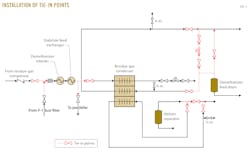
Pioneer enlisted outside help for the detailed engineering and to generate isometric drawings for the new and some existing piping. A brief shutdown was needed to install several critical tie-in points and also to complete some insulation work. These tie-in points were spooled and flanged to minimize downtime (Fig. 5).
Construction began on the tie-in points after the engineering kickoff meeting in mid-February 2012. The materials arrived in late March. The plant was shut down for 2 days to install the tie-ins in mid-May. After the tie-ins were installed, the remaining piping was installed and insulated without a plant shutdown.
Construction was completed and the plant started up with the existing residue compressor KR-104 in the middle of August. The new compressors were installed and started up in early December.
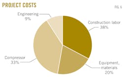
The project was completed for about $4 million. Fig. 6 describes the cost breakdown.
Start-up
During start-up it was important to maintain sales specifications of all plant products. Among these was the increase in methane content in the NGL product due to the change in demethanizer operating conditions. As the project began to recover more ethane and propane, the methane in the NGL product changed.
Changes were made to ensure that the NGL product would meet the spec and that maximum NGLs were recovered. The ethane recovery was estimated at about 80% and the propane recovery was as high as 99%. These recoveries are based on a reflux rate of 9.3 MMscfd.
Another key aspect of the start-up process was that, as more ethane and propane were recovered from the feed, the heating value of the residue gas decreased. The inlet gas to the plant is high in nitrogen.
To raise the heating value, higher flow needs to go through the nitrogen rejection unit.
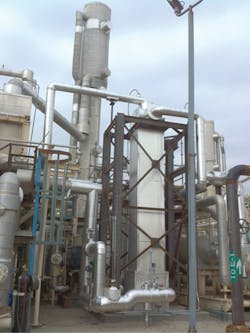
Proper procedure was developed to start up the new brazed aluminum reflux condenser (EP-2313) slowly because the very cold (-160º F.) streams used in chilling the reflux could damage the exchanger from thermal stresses. Fig. 7 shows EP-2313 in front of the demethanizer.
Another part of the process that was watched closely during start-up was the demethanizer and product stabilizer bottoms temperatures. The demethanizer and product stabilizer side reboilers were used in the new process to precool the compressed residue gas en route to the reflux condenser. During start-up, flow rate through these exchangers was low and the trim reboilers had to make up the balance of heat to keep the methane content of the NGLs within specification. There was enough heat available in the trim reboilers that the product was never out of pipeline specification.
With the new design flow rate of reflux to the demethanizer, the existing residue compressor was at its maximum capacity. In order to maintain a lower demethanizer pressure, the compressor had to be adjusted. Several exchangers will need to be cleaned to provide the highest suction pressure possible.
The inlet compressor was also pushed to the limit to obtain high inlet pressure to the plant. Because the plant is operating below the design conditions, it required a significant amount of recycle to keep the centrifugal compressor out of surge.
The authors
Guang Lee ([email protected]) is a process technologist for Bechtel Hydrocarbon Technology Solutions (BHTS) Inc., Houston. He has more than 15 years of experience in cryogenic technologies for gas processing, LNG, and ethylene industries. He holds a PhD in process integration from the University of Manchester and a BSc in chemical engineering from National Taiwan University. Lee is a member of AIChE and the Houston chapter of the Gas Processors Association.
Sudhir Golikeri ([email protected]) is manager of gas processing for BHTS. He previously worked for MW Kellogg, Davy McKee, Amoco and BP. He holds a PhD in chemical engineering from the University of Houston.
Jie Yu ([email protected]) is a process engineer for BHTS. She has worked on various gas processing and LNG related studies. She holds a PhD in chemical engineering from Rice University, Houston.
Patrick Drew ([email protected]) is a process engineer for Pioneer Nature Resources, Dallas. His experience includes working with cryogenic gas plants, gas and condensate gathering, compression, amine absorption, and glycol absorption. Drew holds a BS (2009) in chemical engineering from Texas A&M University.
Bonnie Dumas ([email protected]) is manager of gas processing for Pioneer Nature Resources. She previously worked for Mobil Oil Corp. as a process engineer specializing in fractionation and tower internals. She holds a BS in chemical engineering from Texas A&M University.
Correction"Rapid North American shale gas development pushes up global capacities" (OGJ, June 3, 2013, p. 74), discussing Howard Midstream Energy Partners, incorrectly cited processing agreements as totaling "more than 350 bcfd." The correct amount is 350 bcf. |
