PROCESS SAFETY—1: Gas conditioning failures show need for design scrutiny
Brian Pack
BP America Production Co.
Houston
Aubry Shackelford
Inglenook Engineering Inc.
Sugar Land, Tex.
| Based on a presentation to the Laurance Reid Gas Conditioning Conference, Feb. 24-27, 2013, Norman, Okla. |
Review of certain oil and gas operations offers lessons on process safety to designers of gas conditioning. Those operations include upstream NGL processing, onshore gas conditioning—such as glycol dehydration and amine sweetening, and dewpoint process plants, instead of booster compressor stations, offshore production platforms, and floating production, storage, and offloading vessels.
Part 1 of this two-part series presents four process safety examples of possible inadequate overpressure protection design related to amine sweetening, glycol dehydration, and molecular sieve dehydration. The examples reflect systematic design problems in traditional gas-conditioning overpressure protection analysis and reveal ways to improve future designs.
The concluding article (OGJ, June 3, 2013) discusses opportunities for embedding inherently safer design (ISD) concepts and frequently encountered issues in design of protective systems for these gas-conditioning units.
These examples emphasize the need to raise awareness that designs of gas conditioning systems must do more than simply meet process specification; they must consider robust process safety features dealing with hazardous materials and process conditions.
Switching valve failure
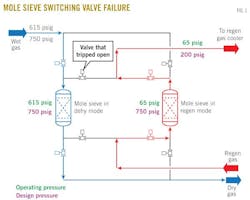
A gas production site employed a mole sieve unit for which the regeneration system was not rated to the same pressure as the drying section. Flaring occurred when a localized failure of the control system caused one of the overhead switching valves to open, allowing 600-psig inlet gas to flow into the regeneration system operating at 65 psig.
The downstream regeneration system was protected by a single rupture disk with a burst pressure of 200 psig and located on the overhead piping of the regeneration gas scrubber. This rupture disk burst in response to the pressure spike.
Pressure continued to rise in the flare header-knockout (KO) drum, requiring operations personnel to cut the feed to the mole sieve beds, stemming the overpressure. While it is important that no physical or sustainable adverse consequence resulted (outside of having to replace the burst disk), the event resulted in mechanical equipment briefly exceeding specified operating design limits.
Fig. 1 illustrates the incident.
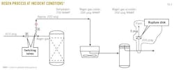
The relief basis indicated that the downstream rupture disk protecting the regeneration system was sized to block flow from inlet gas. Because switching-valve misalignment does not appear to have been considered in design, the relief header was not suited to handle the initial transient flow across the open valve at upstream operating pressure.
In the event a switching valve fails open at normal upstream operating conditions, the relief capacity is about four times the rate for the blocked-flow case. The flare header is rated (limited by the pressure rating of the KO drum) to a capacity less than the rate produced by the switching valve failure.
Fig. 2 shows more detail of this switching valve failure.
The higher transient relief load from the switching valve failure is caused by the volumetric imbalance and pressure imbalance. The volume upstream of the switching valve is 1.3 times greater than the gas expansion volume available in the regeneration section (including the flare header).
Depressuring of this volume at operating pressure to relieve conditions across the fixed flow area of the failed-open switching valve is at a much higher rate than the steady-state flow rate into the plant.
Once the upstream stored volume is exhausted by the higher depressuring rate, the relief requirement becomes the steady-state rate. These two factors explain the continuing pressure rise when the rupture disk burst in the example.
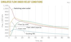
Modeling performed later supported the bottleneck in the relief system during a switching-valve failure. A HYSYS depressuring model was built to simulate the transient conditions described.
Fig. 3 summarizes the results of the model.
When a switching valve fails open, rates and pressures exceed the capacity of the flare system for less than 2 min before steady-state conditions return. During this transient period, the integrity of the relief system may be compromised.
While each owner-operator needs to consider its philosophy for handling transient conditions, the owner of this facility deemed it unacceptable not to provide overpressure protection for this case and formed a team to resolve the issue.
Although it likely would not have altered the decision to modify or accept this original design, the lack of documentation supporting the decision not to consider switching valve failure a credible overpressure case is important and stresses the need for development and lifecycle maintenance of thorough documentation for the basis of overpressure protection.
Much care went into maintaining the basis for the operational design of the mole sieve (original operations and maintenance manuals exist and are in continued use), and the relief design basis must be treated similarly so that it stays evergreen for the entire facility's life.
Proximity to fired heater
In a typical glycol dehydration unit, water is separated from the glycol in a still open to the atmosphere where water vapor leaves the system. The heat supply to the reboiler is commonly a direct-fired gas heater with an exhaust flue stack that may be close to the atmospheric discharge from the still.
During various process upsets, effluent from the still may not be all water vapor but may contain hydrocarbons, and the flue stack can provide an ignition source for that material.
In an example from 2006, a level alarm on a flash separator prompted a shutdown and subsequent drainage of the flash separator. Unfortunately, this drainage was incomplete because condensate was present in the separator during restart of the unit. This condensate was fed into the glycol recovery still.
Upon contact with the heated glycol-water system, the condensate started boiling and exited to the atmosphere via the normal vent on the still. The condensate discharge contacted the nearby uninsulated flue stack, resulting in a fire (Fig. 4).
This example illustrates a common approach to design in which the hazard analysis is limited to considerations found in normal operations. The typical design for a glycol reconcentration system with a direct-fired gas heater, with the exhaust flue stack from the heater close to the atmospheric vent from the still, is not even considered a potential hazard because the normal vented material is water vapor.
As this example shows, however, various process upsets can force hydrocarbons out of the vent, allowing the flue stack to become an ignition source.
Overfilling
The following example resulted in carryover of amine to the flare. While a detailed analysis of the root cause of the occurrence and detailed corrective actions were developed, only a brief summary of the cause and corrective actions taken is presented in this first article of the series.
Fig. 5 shows the pertinent equipment of the amine plant.
The event was initiated by a plugged filter element as a result of "dirty" amine. Field deposits, heat-stable salts, and corrosion particulates had built up over time enough to restrict the outlet of the charcoal filter.
With the inflow to the flash tank greater than the outflow from the charcoal filter, the flash tank began overfilling with rich amine and the pressure rose. There were no high-level or high-pressure alarms on the flash tank, only local gauge indication.
The rich amine overfilled the flash tank and began spilling into the flare header, which transferred the problem to the flare KO drum. Although the flare KO drum was fitted with a high-level alarm, it did not initiate an operator call-out but only alarmed locally within the control room.
The flooded flash tank caused poor gas treatment, which triggered a high CO2 alarm from off-spec NGL in the pipeline; that resulted in an operator call-out. Although the flare header filled with amine, the operator was able to stem its flow before the flare stack was overfilled, averting loss of primary containment.
Several causes led to the event with the most immediate being the charcoal filter plugged by dirty amine.
First, for weeks the increased frequency in cycle time for filter element changeouts had indicated the amine was dirty. Almost 3 months earlier, the filters completely plugged during the day shift. Operations corrected the problem at the time with no adverse consequences. At the time of this incident, the filter elements were being replaced daily.
Second, although the plant was originally designed to be fully staffed, in recent years declining rates and reduced facility complexity led to staffing for a single 12-hr daytime shift. While moving to non-continuously staffed operation is characteristic of ISD philosophy, necessary changes were not made to the design or control scheme to support this operational mode for which increased remote monitoring or active automated control may be required.
Third, a similar event of liquid carryover to the flare (from a different process system) had occurred only 2 years before; the cause was a lack of automated controls. While active mechanical protection or active instrumented protection is preferred to operator's response to an alarm, it is important to recognize that changes to operating philosophy may affect the effectiveness of safeguards.
Although reduction of workforce at the facility promoted the ISD philosophies of minimization and separation, consideration must be given for how such a change affects the effectiveness of mechanical and instrumented safeguards. A key lesson for existing operations is that operating philosophy informs the interdependencies of ISD features, and any change to that philosophy not only affects operation of the equipment, but also may reduce the effectiveness of safety barriers, thereby reducing the overall process safety of the equipment.
As a result of the event, operators at the site cleaned the amine solution and implemented better monitoring of the amine system's health. The design called for installation of high pressure and level alarms and addition to the safety logic of a plant shutdown on pressure high-high and level high-high at both the flash tank and KO drum.
These measures should improve the overpressure protection system at the site but are subject to issues that will be discussed in more detail in Part 2 of this series.
Product breakthrough
In a typical amine unit operation, the rich amine from a contactor column is sent, via a level-control valve, to a flash tank operating at much lower pressures, allowing some of the dissolved gases to flash off.
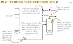
API Standard 521, 5th Edition (2010), §5.10.3, notes that a credible cause of overpressure for the flash tank is failure of the level control valve or loss of liquid upstream, with subsequent flow of the high-pressure gas (known as "breakthrough" or "blow-by") into the flash tank.
In addition, this type of overpressure was highlighted in the US Chemical Safety and Hazard Investigation Board's 1998 investigation into the explosion at the Temple 22-1 Common Point Separation facility in Pitkin, La.
In a recent incident in Red River Parish, La., during start-up of an amine unit, an amine flash tank overpressured when an operator manually set the level-control valve fully open and left it unattended. The flash tank had a pressure-relief valve, but the isolation block valves downstream of the pressure relief device were closed and not opened before the start-up. Without means to relieve the pressure, the amine flash tank subsequently ruptured (Fig. 6).
While initial reaction may be to point to the isolated pressure relief device as the main cause in this example, a closer look reveals several needed improvements. Lack of sufficient isolation/by-pass controls was apparent not only with the pressure relief device remaining isolated during start-up but also with operation of the level control valve.
In addition, the pressure relief device was likely sized inadequately to limit the pressure during the event to the maximum allowable accumulation pressure: The flow rate of a gas through a level-control valve that is normally passing liquid is substantially greater than the normal liquid flow and should be considered fully in the design basis for overpressure protection.
This is yet another example of hazard analysis limited to considerations based solely on normal operation, while the potential for high-pressure gas to flow through the control valve may not have been considered.
The authors
Brian Pack ([email protected]) is a process safety and relief systems technical authority for BP America Production Co., North America Gas Region, Houston, for which he has also served as midcontinent area engineering support team leader. Pack holds a BS in chemical engineering from the University of Oklahoma, is a registered professional engineer in Texas and Oklahoma, and is a member of AIChE.
Aubry Shackelford ([email protected]) is principal engineer and president of Inglenook Engineering Inc., Sugar Land, Tex. He has also served as process technology manager for Lloyd's Register Energy Americas. Shackelford holds a BS in chemical engineering from Northeastern University, Boston, and is a registered professional engineer in Texas, Oklahoma, and Massachusetts, and Alberta. He is also a member of AIChE, SPE, and the National Society of Professional Engineers.


