Altering CP criteria part of unified anti-SCC approach
Hamed Mansoori
Reza Mirzaee
National Iranian Oil Co.
Ferydoun Esmaeilzadeh
Dariush Mowla
Shiraz University
Shiraz, Iran
Altering cathodic protection criteria, repairing coatings on weld joints or the welds themselves, and using coatings less sensitive to disbonding can reduce stress corrosion cracking-induced pipeline failures.
High-density polyethylene coatings are vulnerable to disbonding. Disbonding can be initiated by either cathodic and osmotic conditions or a combination of these. Applying 100-mv polarization instead of the off-potential condition can prevent coating from being disbonded by delivering a less intensive current for protecting the pipe.
External soil stress accompanied by the diffusion of moisture, oxygen, and carbon dioxide under a pipeline coating creates a corrosive environment, initiating cracks into the pipe structure. Fluids flowing at high pressure inside the pipe make this situation worse by propagating the cracks, leading to potential failure and explosion. Without tensile stress, even in a corrosive environment, possible failures appear as pitting, which will not lead to an explosion but instead create leaks.
CP, disbondment
A cathodic protection (CP) system applied to a pipeline can cause coating to be disbonded from the pipe surface. Environmental conditions and subsequent chemical reactions usually cause this to happen. Cathodic disbonding typically starts from damage inside the coating and develops axially around the existing defects. Increased electrolyte pH at the contact point between the pipe and coating causes most coating defects. The pH value at the edge of disbonded coating is often higher, related to the speed of cathodic reactions, cation diffusion speed, and the disbonded area's shape.
Hydrogen reduction reactions in acidic media include oxygen and hydrolysis reactions in cathodic or neutral media, including oxygen. All such reactions increase pH and accumulation of hydroxide ions under the coating. pH value can exceed 12 at the edge of disbonded coatings. In caustic cations, the value of pH for solution can reach 9.2 before being limited by iron hydroxide saturation.
Hydroxide ions near coating holes and under CP can move to the metal-coating contact surface. Such migrations can intensify cathodic disbonding. Factors that help accelerate this process include:
• Weakness in pipeline bed.
• Pipe manufacturing defects.
• Inadequate quality control during pipeline construction.
• Poor material choices.
• Residual applications stress in coating layers.
• Mechanical coating stress from hydrostatic testing.
• Temperature variations during pipe operation.
• Soil stress.
• Diffusion of humidity under the coating during either construction or operation.
Holes and lack of adhesion are the main defects in coating. Such defects can expose the pipe surface to electrolytes. A number of conditions can cause holes or disbonding in coatings. Surface impurities caused by the capture of corrosion products under the coating, combined with the hydrophilic solvents found in the structure of some coatings, may lead to physical and chemical osmosis. In osmosis condition, water can move to the pipe surface via coating.
Water film and the formation of corrosion products under the disbonded coating lead to lowered adhesiveness of coating on the pipes. In some cases in which the coating has no holes, including needle defects, the rate of ion diffusion can be ignored and the rate of cathodic current focused on instead.
Determining if a coating has remained virgin is difficult. Vapor, oxygen, and carbon dioxide can penetrate the coating and reach the pipe surface via several paths, including the coating being scratched by rock, overlap coating, local damage suffered during coating repair and cable connection, and anode scars from cad welding to the pipe. Each of these can reduce CP efficiency on the affected areas of pipe, activating corrosion under the disbonded points.
Corrosion rate is generally associated with oxygen diffusion. It can be accelerated by an increase in temperature and cause a coating defect, creating cathodic shielding and preventing the CP system from efficiently protecting the pipe by reducing cathodic current to the metal surface.
Either an interruption in the electrolyte path between anode and pipe or a long gap between them can create shielding, resulting in a pipe potential that falls short of the required protective potential. This weakness, however, is not detectable in regular inspections and becomes problematic when current density falls below the amount required to protect the pipe surface from corrosion.
Cathodic current can reach the disbonding area through the formed solution layer under the coating. CP that overcomes both the ohmic resistance of the solution layer and polar resistance between the solution and pipe as the distance from the location of holes increases takes on a less negative current potential. When the cations reach the disbonded location, however, anions like chloride become confined, initiating pitting corrosion.1
SCC
Once water, oxygen, and other chemical factors reach the pipe surface via compromised coating, increasing CP current is often the only proper solution for preventing corrosion. This approach is not always effective, however, sometimes allowing corrosion to continue unless the defective coating is repaired or replaced.
Even in otherwise on-spec coatings, deficiencies can be introduced by weakness in the pipe foundation, poor construction techniques, soil and other stresses, lack of harmony between the coating material and environmental conditions, operating temperatures, inexperienced contractors, and poor supervisory and quality control.2
Failed coating adhesion will expose the pipe to cathodic shielding. An acidic environment and pH near neutral develop under the disbonded coating, showing shielding behavior, directly affect pipe cracks. CP shielding with pH near neutral primarily introduces risks such as pitting and general corrosion, microbial corrosion, and SCC.
If defective coating does not hinder cathodic current, then ordinary monitoring of the CP system should be sufficient to ensure pipe quality. If weakness in coating adhesiveness coincides with water penetration under the coating, however, two statuses are possible: partial or complete cathodic shielding. Both lead to corrosion, but the latter involves more aggressive corrosion and thus considerable damages.
Severity and type of corrosion depend in most cases on the electrolyte under the coating, with pitting and general corrosion, microbial corrosion, and SCC in caustic and acidic pH all possible around the longitudinal and peripheral filler wire of the pipe.2, 3 Stress, corrosion, and a crack are all required for SCC to emerge.
Soil stress and environmental corrosion work together in buried pipes to create cracks. A proper internal corrosion monitoring system and optimum use of corrosion inhibitors (CI) can mitigate the effects of both environmental corrosion and stress from the flowing fluid on the inner pipe wall, avoiding initiation of the cracking process. CI manufacturers claim that applying appropriate CI and launching effective monitoring programs can increase pipe resistance to SCC by 12%.4
Case study
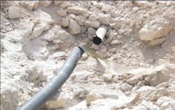
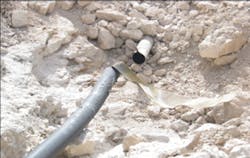
A 10-in. ID pipeline, transferring natural gas from wellhead to a gas gathering unit in southern Iran, exploded due to what was determined to be SCC. A corrosive environment under the disbonded coating combined with stresses from soil around the pipe caused slight cracks to form. Stresses from fluid flowing in the pipe helped crack development and led to SCC and the explosion (Figs. 1-2).
SRB
Initial theories suggested sulfate reducing bacteria (SRB) might have helped intensify the corrosion that led to the pipe burst, prompting experiments to measure SRB quantities in the surrounding soil.5 Technicians dissolved soil samples into sterilized, distilled water. The bacteria test kits were stored at 30° C. ambient temperature for 48 hr. Results revealed no SRB in the sample soil around the damaged pipe.
DCVG, CIPS
An underground pipe protected by a cathodic system would be connected to the earth where its coating is ruined. Protective current will enter the pipe from soil through the ruined coating. Operators can ignore the amount of protective current used when coating is undamaged. The resistance encountered entering current into the pipe via soil, however, causes voltage loss around the damaged coating, forming concentric circles with different potential.
Voltage loss gradient is proportional to the severity of coating damage. Severely damaged coatings lead to higher voltage gradients. Voltage gradient is also a function of soil resistance around the damaged coating. The processes described in this article used close internal potential systems (CIPS) and direct current voltage gradient (DCVG) procedures to monitor CP and coating quality. CIPS includes measuring potential in close intervals of pipe. Tests measured RECT OFF instant-off potential as higher than the 0.85 v desirable for CP, with multiple instances of damaged coating.
Measures taken
The explosion called for pipe excavation and external corrosion direct assessment (ECDA) to secure the safety of both personnel and production. Excavation occurred 200 m from wellhead sites and gas gathering units. Tape wrapping followed ECDA and sand blasting, applying an inner layer of three-ply polyethylene coextrude material and an outer layer with 50% overlapping. Holiday detector testing preceded pipe backfill in accordance with NACE RP0188.
NACE standards recommend a 100-Mv polarization shift criterion to avoid future disbondment.6 Non-shielding coating was also recommended for the pipe repair. Time limitations, however, dictated using the three-ply PE coextrude coating instead.
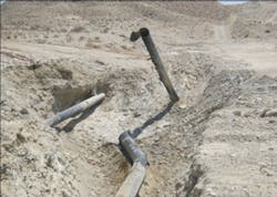
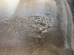
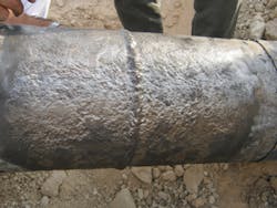
The accompanying table summarizes ECDA activities and coating repairs. The change in CP criteria and repairing high-risk areas should limit the likelihood of future SCC-caused failures. Grades C and B denote corrosion conditions requiring attention. Most damage occurred on sections of pipe using heat shrink sleeves (HSS) as coating due to disbonding and current shielding (Figs. 3-4). The table also makes clear the need for regular inspections, both non-destructive testing and visual, to monitor the external corrosion status of pipes.
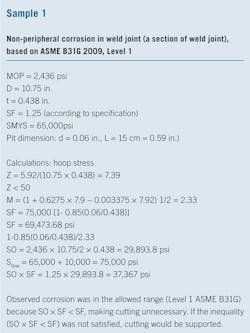
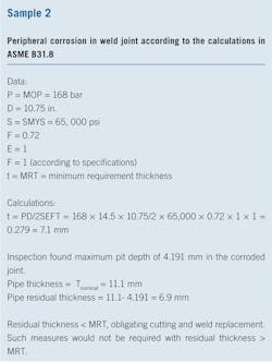
The accompanying boxes provide sample calculations from two of the pipeline's weld joints.
References
1. Jones, D.A., "Principles and Prevention of Corrosion," Macmillan Publishing Co., New York, 1991.
2. API 581, "Risked Based Inspection, Base Resource Document," 1st Ed., May 2000.
3. NACE RP0502-02, "Standard Recommended Practice, Pipeline External Corrosion Direct Assessment Methodology," 2002.
5. Fontana, M.G., "Corrosion Engineering," Noida, India: Tata McGraw-Hill, 2005.
6. NACE Standard RP0169-96, "Standard Recommended Practice, Control of External Corrosion on Underground or Submerged Metallic Piping Systems," 1996.
The Authors
Hamed Mansoori ([email protected]) has more than 9 years' experience with National Iranian Oil Co. (NIOC) as process engineer. He holds a BS in chemical engineering from Islamic Azad University, Iran, and an MS in chemical process engineering from Shiraz University, Iran. He coordinates industrial projects jointly with Shiraz University and NIOC for southern Iranian oil and gas fields.
Reza Mirzaee ([email protected]) is a senior corrosion engineer at NIOC with 11 years' experience. He received his MS in chemical engineering from Isfahan University of Technology, Iran, and holds a BS in chemical engineering from Tehran University.
Feridun Esmaeilzadeh ([email protected]) is associate professor at Shiraz University, joining in 2002, and adjunct professor at the Sharif University of Technology since 2001. He served as visiting professor at Georgia Institute of Technology, Atlanta, 2010-11, and the Petroleum University of Technology and Isfahan University of Technology, 1994-2002. He has more than 10 years' experience at NIOC as an administrator of reservoir simulation, production engineering, and petrophysics. Esmaeilzadeh holds a BS (1986) from the Abadan Institute of Technology, Iran, an MS (1990) from Shiraz University, and a PhD (2001) from Sharif University of Technology, Tehran, all in chemical engineering. He is a member of the Society of Petroleum Engineers and the Iranian Association of Chemical Engineering.
Dariush Mowla ([email protected]) is professor of chemical engineering at Shiraz University and head of the school's Environmental Research Center in Petroleum and Petrochemical Industries. Mowla earned his PhD (1991) from INP de Toulouse, France, and joined Shiraz University in 1992. He has served as visiting lecturer or professor at Oklahoma State University (1990-91), the University of Queensland (1998), and the University of Toronto (2012).
