New method uses hardness to find yield strength
Shadie Radmard
Monique Berg
Enbridge Pipelines Inc.
Edmonton
Based on presentation to ASME's International Pipeline Conference, Calgary, Sept. 27-Oct. 1, 2010.
A new method to determine yield strength based on hardness could be used in storage facility pipes with results more conservative than outlined in CFR Title 49 Part 195.106.
The US Pipeline and Hazardous Materials Safety Administration (PHMSA) approved the methods of determining yield strength and maximum operating pressure described in CFR Title 49 Part 195.106 before the testing described in this article, results of which were presented to PHMSA in several meetings between September 2009 and February 2010.
Background
Enbridge's Cushing, Okla., tank location includes 488 pipe segments. Of these segments, about 70% (338 segments) had inadequate pipe records (including pressure-test records) when Enbridge bought the location in 2004. All segments lie wholly within the Enbridge Cushing site and not in high-consequence areas.
The pipe segments at Cushing range from 3 to 30 in. OD and were put into service between 1920 and 2004. These pipes have varying WT and lengths and include many pipe configurations within the tank location.
In 2005 Enbridge retained Willbros Engineering to create a risk-management plan for pipelines within the three terminals at Enbridge's tank facility. These data included OD, location, and line use information (i.e., daily use, rarely used, or completely idle).
In 2007, Enbridge began a pipe verification project to determine the yield strength (YS) in psi and allowable working pressure (AWP) in psig of this piping.
Enbridge then reviewed all available pipe records for the Cushing site, along with the data provided by Willbros Engineering to confirm the following for pipes greater than 12-in. OD:
• X-56 pipe was the highest-rated.
• X-35 or Grade B was the lowest rated.
• WT ranged from 0.25 to 0.5 in.
Determining the scope of the project required Enbridge to meet the requirements of CFR Title 49 Part 195.0.
About 338 pipe segments, at all three Cushing terminals, were missing some key pipe information (WT, YS, maximum operating pressure) including hydrotest records.
ASTM A 370-09 standard provided information regarding hardness as a means of determining tensile strength (Section 15.1) and validating the use of portable hardness testers (Section 18.1).
Enbridge then used this information in the preliminary stages of pipe verification to determine project duration and budget.
Project scope
Information collected and assessed from the available records prompted Enbridge to undertake the Cushing Pipe Verification Project to determine YS of piping with inadequate pipe records and whether these pipe segments could be deemed low stress at existing operating conditions.
Various standards and reports guided determination of what would be an industry accepted standard to determine YS while meeting the requirements of CFR Title 49 Part 195. Two documents (reviewed and described below) validated the use of hardness testing as a means of determining pipe YS.
• ASME CRTD Vol. 57—"Determining the Yield Strength of In-Service Pipe." In December 1999, ASME prepared a report to support the use of hardness as a means of determining yield stress of in situ pipe. ASME established a correlation between lab hardness and YS, and subsequently established a correlation between field hardness and lab hardness. It established an overall field hardness to YS at different confidence levels, for a specific piece of field testing equipment for transmission piping rated X-52 or less. The ASME report established a 99% confidence level and a 0.5 percentile lower bound.
• Pipeline Research Council International, Inc., Final Report R 1081-01R—"In Situ Mechanical Property Characterization" (prepared by CC Technologies Laboratories Inc.). In March 2005, CC Technologies (now called DNV Columbus Inc.) prepared a report that further supported the ASME findings.
CC Technologies stated that the ASME approach for YS determination was valid but that each company using this technique would have to determine a statistical correlation between field hardness and yield strength for the particular field hardness tool being used. This report also concluded that the ASME confidence level (99% and a 0.5 percentile lower bound) was too stringent and that using a statistical level of 95% confidence and a 1 percentile lower bound was more reasonable.
A final method of determining YS for piping of unknown SMYS involves using the method described in CFR Title 49 Part 195.106(b), whereby the YS is determined with randomly selected specimens with a specific number of lab tests to determine yield-tensile ratios. A later section of this article will describe this determination.
These two reports and CFR Title 49 Part 195.106 established the following scope of work:
• Obtain field hardness, OD, WT, and seam joint factor data for all Cushing Terminal Piping with missing records.
• Obtain pipe coupons for various ODs and obtain field hardness, lab hardness, WT, and yield-tensile ratios in accordance with CFR 195.106.
• Establish a field hardness-to-YS correlation using pipe coupons from the Cushing facility as well as coupons from another Enbridge piping system.
• Convert the actual field hardness measurements to YS for the 338 pipe segments.
• Determine YS using the yield-tensile method described in CFR Title 49 Part 195.106 for the 338 pipe segments.
• Once YS was determined for each pipe segment, determine if the segment could be considered low-stress at the existing maximum operating pressure of 275 psi.
• For piping that could not be classified as low-stress at 275 psi, calculate the AWP required meeting low-stress criteria.
Field hardness
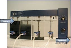
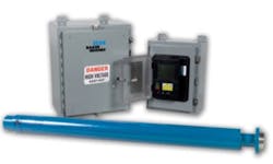
Two different portable hardness testers verified hardness, a Telebrineller Hardness tester (Fig. 1) and a MIC 10 Hardness Tester (Fig. 2).
This hardness tester uses one hammer blow on the anvil. The impact transmits equally to the test bar, through the impress ball to the specimen metal (Fig. 1).
The Telebrineller system uses one hammer blow on the anvil. The impact transmits equally to the test bar, through the impress ball, to the specimen metal. The diameters of the resulting impressions are directly related to the hardness of the test bar and specimen. MIC10 testing uses the UCI Method (Ultrasonic Contact Impedance) with a Vickers diamond indenter.
The pictured hardness testing equipment uses ultrasonic contact impedance with a Vickers diamond indenter (Fig. 2).
Once the methods of determining YS and field hardness were selected, Enbridge addressed the following administrative activities:
• Creating forms for data collection in a format that would be suitable for permanent records.
• Creating a site map with proposed dig locations.
• Determining excavation sites to maximize the likelihood of exposing more than one pipe in a single trench.
• Determining project start date and duration based on availability of equipment and labor.
• Selecting a contractor with the knowledge and experience to conduct hardness testing, assess pipe condition, and determine pipe WT and seam type.
Activities, calculations
The field portion of this project was completed Oct. 16, 2007-Aug. 14, 2008, by PfiNDE Inc., which measured pipe segments at 345 locations (digs) for field hardness. Where possible, PfiNDE exposed pipe at two different sites for verification purposes. Testing using the Telebrineller hardness tester and the MIC 10 hardness tester followed exposing the pipe and sandblasting it per specification.
Fig. 3 shows the axial positions of test samples for the MIC10 hardness tester. Each axial location was sampled five times.
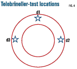
Fig. 4 shows the axial positions of tests conducted for the Telebrineller hardness tester. Each axial location was sampled five times. It is impractical to obtain hardness samples at the pipe's 6 o'clock quadrant with the Telebrineller tester.
PfiNDE Inc. had to collect the following pipe information: WT, seam weld type, pipe condition, coating, hardness value, OD, and location. The electronically recorded information received a file number for tracking purposes. PfiNDE took before and after photos of the excavation and pipe.
The site inspector was responsible for completing specific forms of the report to identify pipe condition, configuration, and site description, as well as taking photos of the excavation before pipe sandblasting to identify pipe coat conditions. PfiNDE was also responsible for taking photos of the pipe, mainly to show pipe condition, seam-weld type, and area of hardness testing after the pipe had been sandblasted. Established field testing protocols consisted primarily of surface preparation procedures, involving pipe grinding and polishing for testing purposes.
PfiNDE collected the data for all three Cushing terminals. Removing the high and low data points and taking the average of the remaining readings determined the MIC 10 Brinell hardness and Telebrineller hardness for each dig.
Table 1 shows a sample of the data.
While PfiNDE collected the field hardness and other data for the in situ piping, coupons of 12 pipes of various OD recently abandoned by the terminals were sent to DNV Columbus Inc. to establish field hardness (using the same equipment used to collect field hardness of in situ pipe segments), lab hardness, YS, and tensile strength (following API 5L specifications) to meet the following requirements:
• ASME and PRCI hardness testing methods. A correlation between field hardness and lab YS for the specific field equipment used (i.e., the Telebrineller and MIC 10 Hardness testers) is required.
• CFR Title 49 Part 195.106. Tensile tests are required on a specific number of pipe lengths to accurately determine YS.
Meeting the criteria set out in CFR 195.106, required defining a pipe length as one pipe segment. The 12 coupons exceeded the requirements of CFR Title 49 Part 195.106(b)(1)(i)(Table 2).
In addition to the 12 Cushing terminal samples, 22 samples were sent from Enbridge Spearhead pipeline for additional field hardness and lab YS data required to establish a linear correlation.
The samples helped create a correlation between field hardness and YS for the Telebrineller field equipment, which was then used to gather the 345 in situ field hardness measurements.
A strong statistically significant predictive linear relationship exists between field Brinnell hardness and YS (Fig. 5).
The solid black line represents the prediction equation giving the best estimate of YS from Field Brinell hardness. The two dotted lines are 95% prediction intervals regarding the regression line.
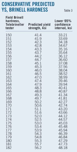
Table 3 shows a sample from the table of the predicted YS and the lower 95% confidence interval from the Brinell hardness for the Telebrineller equipment used for this project. All statistical analysis was performed by DNV Columbus Inc.
The results from the predicted YS at the lower 95% confidence interval helped determine YS for all 338 segments of pipe.
Calculating the hoop stress and using it to determine if the pipe could be deemed low stress followed determination of the YS for all pipe segments.
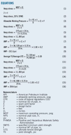
Equation 1 calculated hoop stress.
Maximum operating pressure was set at 275 psi, the existing MOP of the Cushing terminal.
Diameter, "D," was the nominal OD determined from the dig.
Determining nominal WT, "t," for each pipe thickness took the average WT determined in the field and used the closest nominal WT while meeting requirements of CFR Title 49 Part 195.106: minimum WT may not be less than 87% of the value used for nominal WT.
Once hoop stress is calculated, Equation 2 must hold true for a segment to be low-stress piping.
This test used derived YS (in lieu of SMYS, as per CFR Title 49 Part 195.106(b)) for each pipe segment and found 40% of the piping with missing records could be deemed low stress and remain at an MOP of 275 psi.
Pipes not deemed low stress used a calculated allowable working pressure (AWP) to render the pipe low stress. CFR Title 49 Part 195.106(a) calculated AWP (Equation 3).
WT, "t", was the nominal WT determined as described above. YS used field hardness correlation and diameter, "D," equaled nominal OD of the pipe determined during the excavation.
The seam joint factor "E" used CFR Title 49 Part 195.106(b)(2)(e). The Cushing facility piping had a seam joint factor of 1.0, verified in the field as one of the following three pipe classes:
• Seamless.
• Electric-resistance welded.
• Electric-flash welded.
A design factor, "F," of 0.2 (i.e., 20%) ensured the piping could be deemed low stress.
Calculated allowable working pressures for Cushing lie between 128 psi and 275 psi, ensuring the piping could be deemed low stress.
Hardness method
Fig. 6 shows dig location Dig No. 083-20, which exposes a 20-in. OD line.
Dig site No. 083-20 at Enbridge's Cushing tank facility exposed a 20-in. OD pipe for hardness testing (Fig. 6).
Applying the hardness technique's methodology yields the following for Dig No. 083-20:
• Nominal OD = 20 in.
• Seam type: Electric-resistance welded.
• Seam joint factor = 1.00.
• Average Brinell field hardness = 161 (from 15 readings).
• Actual pipe WT = 0.28 in.
• Nominal pipe WT = 0.25 in.
Determinations
Using the correlation between field hardness and YS from the linear regression shown in Fig. 5, a field hardness of 161 corresponds to YS of 38,520 (at the 95% confidence interval) for the Telebrineller equipment used (Table 3).
Equations 4-6 calculate hoop stress.
For stress to be deemed low, the following must hold true:
• Hoop stress <20% SYMS (or YS in this case).
• Hoop stress <0.20 × 38,520 psi.
• Hoop stress <7,704 psi.
In this case 11,000 psi >7,704 psi and therefore the piping is not low stress when operating at 275 psi.
In order for this pipe segment to be considered low stress, the AWP of Dig No. 003C-20 must be that calculated by Equations 7-9.
Under the hardness method, the 20-in. pipe segment at Dig No. 083-20 can operate as a low-stress pipe if its AWP <192.6 psi.
CFR method
A second method also determined YS, the CFR Title 49 Part 195.106 method. A sample calculation using Dig No. 083-20 demonstrates how this technique was used for the pipe verification project.
Determining the YS using CFR Title 49 Section 195.106 requires lab YS and ultimate tensile strength (UTS) for pipe coupons. Table 4 shows a sample of results from DNV Laboratories Inc. for four of the 12 pipe coupons tested.
Dig No. 083-20 produced the following results:
• Nominal OD = 20 in.
• Seam Type: Electric-resistance welded.
• Seam joint factor = 1.00.
• Average Brinell field hardness = 161 (from 15 readings).
• Actual pipe WT = 0.28 in.
• Nominal pipe WT = 0.25 in.
• 20-in. pipe coupon information (see Table 4):
—YS1 = 49,600 psi.
—YS2 = 52,500 psi.
—Average YS = 51,100 psi.
—UTS1 = 74,000 psi.
—UTS2 = 74,000 psi.
—Average UTS = 74,000 psi.
Determinations
To meet criteria of Part 195.106, the YS/UTS ratio must be calculated for the 20-in. pipe coupon (Equation 10).
If the result is less than 0.85 (which in this case is true), then the YS shall be taken as the lower of 80% of the average YS or the lowest YS determined by the tensile tests.
In this case 80% of the average YS = 0.80 × 51,100 psi = 40,880 psi and the lowest YS = 49,600 psi.
Therefore the YS to be used for 20-in. pipe is 40,880 psi.
Equations 11-13 calculate hoop stress.
For stress to be deemed low, the following must hold true:
• Hoop stress <20% SYMS (or YS in this case).
• Hoop stress <0.20 × 40,880 psi.
• Hoop stress <8,176 psi
Since 11,000 psi >8,176 the piping is not low stress when operating at 275 psi.
In order for this pipe segment to be considered low stress, the AWP of Dig No. 003C-20 must be as defined in Equations 14-16.
Using the CFR Title 49 Part 195.106 method, therefore, the 20-in. pipe segment at Dig No. 083-20 can operate as a low-stress pipe if its AWP is less than 204.4 psi.
Results
Using the YS determined through the field hardness-yield strength correlation, pipe yield strengths at Cushing measured 24,000-56,400 psi, with 40% of pipe segments considered low stress at the exising maximum operating pressure of 275 psi. Allowable working pressures calculated for the remaining piping ranged between 128 and 275 psi. Table 5 shows the AWP ranges for pipe segments at the Cushing tank facility determined using the hardness technique.
Verifying that the hardness technique used to determine YS was valid required determining YS for pipes with missing records using CFR Title 49 Part 195.106. This method determined about 58% of piping at the Cushing facility to be low stress at the existing MOP of 275 psi. Table 6 shows AWP ranges using the CFR Title 49 method for pipe segments at the Cushing facility.
YS and AWP results derived through the hardness technique were more conservative and used only to validate the CFR Title 49 Part 195.106 method.
Enbridge complied with CFR Title 49 Part 195 by:
• Lowering maximum operating pressures to that required to meet low-stress conditions (such as lowering MOP for the pipe segment associated with Dig No. 083C-20 from 275 psi to <204.4 psi).
• Successfully hydrotesting lines where a lower pressure (MOP <275 psi) was not feasible, completing hydrotesting on 22 pipe segments by February 2010.
Hardness as a means of determining YS has not been widely used in industry. No clauses in CFR Title 49 Part 195, allow for the use of field hardness as a means of determining YS. CFR Title 49 Part 195.106, therefore, determined YS and AWP of all pipe segments at the Cushing terminal. OGJ
References
1. US Department of Transportation, Title 49, Transportation, Chapter I—Pipeline and Hazardous Materials Safety Administration, Part 195, 2009.
2. Pipeline Research Council International Inc., Final Report R 1081-01R, "In Situ Mechanical Property Characterization," prepared by CC Technologies Laboratories Inc., Mar. 9, 2005.
3. ASME Report CRTD Vol. 57, "Determining the Yield Strength of In-Service Pipe," December 1999.
4. ASTM A 370-09, "Standard Test Methods and Definitions for Mechanical Testing of Steel Products," 2009.
The authors
More Oil & Gas Journal Current Issue Articles
More Oil & Gas Journal Archives Issue Articles
View Oil and Gas Articles on PennEnergy.com
