ESP—Conclusion: Multiple factors affect electrical submersible pump run life

Joe Vandevier
Baker Hughes Inc.
Houston
To achieve a good electrical submersible pump run life, one needs first to understand the key factors that affect the system's run life and then effectively manage those factors.
This concluding part of a two-part series on ESPs will cover 10 of the most important factors to consider in extending ESP run life. The first part (OGJ, Oct. 4, 2010, p. 76) discussed run-life measurements and also summarized what various producers have reported about ESP run life in technical papers.
Although there are a number of potential factors to consider, this article will discuss the following 10 factors:
1. Equipment sizing, selection, and operation.
2. Power quality.
3. Well deliverability and inflow performance.
4. ESP operating temperature.
5. Solids production.
6. Free gas in pump.
7. Depositions.
8. Corrosion.
9. Equipment monitoring and surveillance.
10. Continuous improvement processes.
Equipment sizing, selection, operation
ESPs are engineered electromechanical systems having multiple components and materials. The pumping end of the ESP system is a multistage centrifugal pump with a specified flow range required to ensure high efficiency and proper thrust balance across the many pump stages. Operating the pump outside its specified range can cause either a serious downthrust or upthrust condition that results in premature wear of the pump stages.
Although several solutions can address this condition, the first and most fundamental step is to ensure proper pump sizing. Proper sizing requires good well data that credibly represents the well fluid properties and inflow performance of the well.
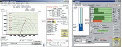
Use of ESP-sizing programs is important because these programs allow use of multiple correlations for fluid properties and two-phase flow that aid in predicting pumping conditions on a stage-by-stage basis through the pump. In addition, ESP application software tools can contain sophisticated simulation and what if features. These features allow the modeling of transient conditions such as ESP start-up as well as changing conditions and subsequent effects on ESP system performance and potential life.
AutographPC is one example of several widely used software tools available from major ESP suppliers and third-party providers (Fig. 1).
Proper equipment selection, however, goes beyond sizing. ESP users often may underestimate the potential well problems that may develop as well inflow increases and reservoir pressure declines due to use of ESP systems. To gain the necessary ESP equipment robustness and operating flexibility, one needs to anticipate harmful well conditions and select the appropriate metallurgies and equipment configurations to handle those conditions effectively.
Unfortunately, properly selected ESP equipment will bring little benefit if improperly installed and operated. Competent ESP system assembly, installation, and commissioning are critical as first steps in deployment.
ESP service technicians must be competent at a multitude of electrical, electronic, and mechanical skills. They must also have knowledge of the specific equipment being installed.
ESP installation also centers on the competency and experience of the rig crew. Crews with limited ESP experience can easily damage system components, cable, and connectors as they run the ESP system to setting depth.
Consequently, successful ESP installation requires experienced and trained personnel involved in installation and commissioning.
Power quality
The ESP prime mover is a unique polyphase induction motor that uses a sophisticated, high-tech insulation system to ensure long life under demanding conditions. The importance of acceptable power quality is crucial for ensuring long-term motor performance.
In many cases, companies install ESPs in remote fields where power quality suffers from outages, poor voltage regulation, high harmonic distortion, single phasing, and transient voltage conditions. Although ESP motors generally can tolerate poor power quality for a short time, these conditions if not corrected will result eventually in insulation breakdown in the motor due to either high voltage or heat degradation of the insulation.
Achieving acceptable power quality is a result of working with the power supplier to ensure adequate supply capacity and good power transmission design. Additional key items on which to focus include ensuring that the system has competent lightning and transient voltage protection with a good power factor and voltage regulation.
The presence of poor power quality usually is straight forward to detect. Early signs of potential problems include a high incidence of motor failures, unexpected well and field shutdowns, and recurring electrical alarms for high voltage, low voltage, voltage unbalance, loss of phase, and high currents.
When these incidents occur, the operator can install a power quality meter on the system to record power delivery conditions over time. Use of this monitoring device helps in analyzing the type of problems occurring and aids in showing a utility supplier that an ongoing power quality condition does exist.
Well deliverability
Producing wells can be quite dynamic, especially in their early lives. Completion engineers usually size ESPs to produce a specific flow range with a given required lift based on expected well productivity. Where scale formation, reservoir flow dynamics, changing field injectivity, wellbore skin effects, or completion problems substantially alter well fluid delivery, the ESP may operate outside its intended range. This quickly can lead to premature failure. If one anticipates a wide range of dynamic well conditions, the ESP system design can include a variable-speed operation that allows a much broader operating range (Fig. 2).
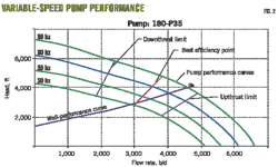
Fig. 2 represents the system solution for a producing well operated with a 180-stage P35 pump on a variable-speed drive. Since the pump can operate at multiple frequencies, the curve provides a visual solution to find the point at which the system curve intersects the pump curve for a given frequency. For example, if the pump operates at 50 hz, the flow rate will be about 2,900 b/d at a 2,900 ft of total dynamic lift. On the other hand, if the frequency increases to 65 hz, then the pump will produce about 4,600 b/d at the 4,000 ft of total dynamic lift required by the well and specific completion to produce this flow rate.
Besides providing the simplicity of dialing in different flow ranges, a VSD extends the thrust range of the pump.
Fig. 2 also shows the pump's recommended downthrust limits, upthrust limits, and best efficiency point as continuous lines for each frequency. Notice how the thrust range window moves to the right as the frequency of operation increases. This is extremely important in keeping the pump in a more favorable thrust condition across a larger flow range than merely overstaging the pump and then using a surface choke to control flow.
Operating temperature
ESP systems have a broad range of application temperatures. In many cases, the well temperature is benign (<200° F., 93° C.), while in steam-assisted gravity drainage and other steam-assisted production applications, the fluid temperature can be greater than 400° F. (204° C.).
Completion engineers select final equipment design based on the expected equipment operating temperature. If the operating temperatures exceed the maximum ratings for the particular ESP system deployed, a system failure is likely.
The ESP operating temperature used in the design is based primarily on the dynamic well temperature and the effect of produced fluid flowing between the ESP unit and the casing. An operating temperature exceeding the ESP's design rating can reduce the expected life because of the following three primary mechanisms.
1. The motor's insulation system has a thermal rating that if exceeded for any extended period results in an exponential life reduction (Fig. 3). The general rule for insulation systems is that each incremental 18° F. (8° C.) above the thermal rating decreases the dielectric life expectancy in half. It is crucial, therefore, to ensure the motor's insulation remains within its thermal rating. This can be done by monitoring and controlling both the well and ESP equipment and regulating ESP operation based on the operating motor's temperature.
2. Where the operating temperature exceeds the ESP design rating, the elastomers used for sealing the ESP from wellbore contamination can deteriorate, resulting in well fluid entry into the unit. When this happens, a catastrophic failure generally results as well fluid destroys bearing surfaces and deteriorates insulation dielectric.
3. Exceeding the rated operating temperature can create a significant difference in component expansion. The design of an ESP's rotating mechanics are within certain clearances and running tolerances, and high operating temperatures can create inadequate clearances within the ESP system, causing entry of well fluids or binding and galling of rotating parts.
It is worth noting that a VSD is an important tool for controlling motor-insulation temperature. Speeding up or slowing down the pump can adjust the rate the produced fluid flows past the motor. In addition, reduced-frequency starting can greatly assist in lowering motor temperature rise during system starts, especially when the pump requires multiple starts.
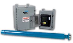
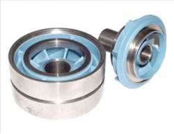
Fortunately, new technology and applications continue to improve the protection of an ESP system from high temperature. These developments include improved pump selection and application software tools as well as the continuous monitoring of the ESP system with downhole sensors (Fig. 4) that measure several key parameters including motor temperature, well temperature, pump discharge temperature, pump intake pressure, pump discharge pressure, and motor vibration.
These sensors ensure an ongoing understanding of well productivity and ESP operating conditions. Use of downhole sensors has increased rapidly as companies have experienced the value of identifying ESP operating problems before they become catastrophic.
Solids production
Many oil wells produce a small amount of solids such as sand particles, scale, or precipitants. ESP pump components can withstand a wide range of solids concentrations based on well conditions.
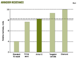
For low-solid content in the flow, the pump metallurgy is primarily nickel-iron that is quite hard and resists corrosion. For moderate amounts of solids in the flow, the pump configuration typically has hardened radial bearings. For more aggressive wells, the pump material and design technology uses tungsten carbide or ceramic materials in both radial and thrust bearing surfaces. Also the use of hardened coating technologies such as Armor X (Fig. 5) addresses surface abrasion and erosion. These materials are effective in extending ESP run life.
Although a range of materials is available for handling solids, it remains beneficial to remediate solids production via sand-control completion methods such as gravel packing or application of expandable screens. It is also important not to underestimate that the well's propensity to produce solids in the early production stages when production will increase after installation of an ESP. Experience has shown that it takes time for a well to stabilize at the greater production rate.
During commissioning, some wells produce substantial amounts of solids causing havoc with ESP systems. One can often mitigate this situation by using a well-commissioning procedure that starts production at a lower rate and then gradually increases it to the target rate over days or weeks.
Applying such a start-up procedure with a newly installed ESP reduces the reservoir sweep forces that dislodge unconsolidated sand and allows formation stabilization with lower sand production rates during the commissioning period. Once the well reaches the target flow rate for cleaning up the well, the ESP will be operating with a lower solids concentration in the flow.
Gas production
It is well known that centrifugal pumps are efficient at moving liquid but can quickly gas lock with small amounts of free gas. In many ESP applications, the reservoir pressure remains at or above bubblepoint with no free gas present so that the operation has few problems. As the reservoir matures and pressures drop below bubblepoint, however, an increasing amount of gas comes out of solution, and some of this free gas must be produced by the ESP.
Early solutions to avoiding gas locking of ESPs included the use of reverse flow intakes that used gravity effects to separate and send some free gas up the annulus instead of through the pump. Later, manufacturers introduced tapered pumps that used large-capacity pump stages at the intake to avoid gas locking and also provide incremental fluid compression to the smaller stages farther up in the pump.
These configurations succeeded in increasing the gas-handling capabilities but still could not provide the level of gas handling desired.
Fortunately, several technology improvements over the last decade have extended an ESP's ability to handle fluids with high gas content. Key to achieving this capability has been the evolution of highly effective rotary gas separators in conjunction with development of novel pump configurations that handle more gas without gas locking. The combination of gas-handler stages and rotary separators is allowing ESPs to produce effectively and reliably in wells having gas void fractions of 80% and beyond (Fig. 6).
The effects of high levels of gas on elastomers used within ESP systems are a special concern. In particular, high levels of gas in solution can lead to the elastomeric parts contained in critical seals and cable insulations to absorb gas. As the ESP lowers the bottomhole pressure below the bubblepoint, gas begins to come out of solution and may destroy the integrity of the elastomer through decompression. This results in electrical failure of the motor or cable.
To address this problem for higher gas-void fractions, manufacturers have developed both special elastomer formulations and special elastomer reinforcements
Deposition
Deposits of scale, asphaltenes, or paraffin can cause problems for ESPs. Each type of deposit results from different physical or chemical mechanisms and chemical reactions in the reservoir and well. These deposits, however, are similar in that they usually occur later in the well's life cycle. They appear when changes in reservoir pressure, fluid chemistry, and water production reach a critical point that precipitates the problem.
Unfortunately, their presence impacts the ESP system in a similar fashion. When deposition occurs, deposits build up on pump surfaces causing pump vanes to plug and running clearances to close up. Mechanical wear in the pump, therefore, escalates while the lower flow rates retard motor cooling and increase motor temperature. If left uncontrolled and untreated, these problems will lead to pump locking or motor-insulation failure or both.
Scale has the additional characteristic of being an abrasive deposition that also causes accelerated wear in the exposed running parts of the ESP. The pump wear caused by this abrasion can compound the plugging effects and produce even quicker failure of the system.
Fortunately, there are several solutions that can mitigate failures due to scale and deposition. One example is to coat the stages with special materials that retard deposition buildup. Fig. 7 shows a coated impeller and diffuser surfaces (blue in color) that reduce deposition and can enhance pump life.
The effective use of continuous chemical injection to address deposition problems has expanded during recent years with new developments. Key advances in both chemicals and chemical-injection-system monitoring and control have made this solution attractive for reducing or eliminating ESP failures due to both deposition and corrosion.
Note, however, that when one uses chemicals in the well for any reason (including to kill the well), it is important to consult the ESP manufacturer to ensure compatibility of the elastomers in the ESP system with the chemical.
Corrosion
The effect of corrosion on ESP life varies depending upon severity. Unchecked, it can lead to holes in tubulars and metal components that destroy the integrity of the ESP system.
Where corrosion is severe, manufacturers can provide an ESP with optional high-chrome metallurgy for housing and bar stock parts. The enhanced metallurgies have demonstrated excellent results in substantially increasing run life in severely corrosive conditions.
For moderate corrosion, a metallized or polymer coating applied to the outside of the ESP components can be effective. Also, chemical treatment of the well via continuous injection or batch treatment also can help mitigate the harmful effects.
Equipment monitoring, surveillance
As previously noted, use of downhole sensors has rapidly expanded as an effective tool for improving ESP run-life performance. Sensors used in conjunction with surface monitoring and surveillance tools allow key ESP and well operating parameters to be acquired, stored, and evaluated continuously. This provides a powerful real-time tool for allowing operators continuously to keep up with the health of both the ESP and the well.
By automatically identifying wells or ESPs in distress, the monitoring and surveillance system allows the production engineer to spend less time hunting for problems and more time resolving problems that extend run life.
Also, on a practical basis, use of monitoring and surveillance systems enables the engineer effectively to manage more producing wells than in the past. Given the decline in availability of skilled personnel in the industry, this benefit alone can be an important reason for using these systems.
Incorporated into current monitoring and surveillance systems are alarming, reporting, graphing, and trending features that help ensure timely knowledge of operating conditions. Also now offered are expert systems that use both rule-based and neuron-network artificial intelligence methods to analyze and predict both system health and system life while providing key input for ensuring optimized production. Vision is one such tool available to provide real-time monitoring of well performance and ESP health (Fig. 8).
Continuous improvement
The last key element discussed is the execution of a continuous improvement program aimed at achieving and exceeding ESP run-life targets. Although it is probably obvious why a continuous improvement program is key to increasing ESP run life, such programs can vary widely; therefore, it is worthwhile to describe some of the common elements that make up a successful program, such as:
• Make ESP run-life improvement a team goal. A variety of people or groups can affect the overall run life for an ESP system. This includes the operator's reservoir, production, and facilities engineers as well as workover rig personnel and ESP service providers. There is no substitute for good planning integrated with good information, design, procedures, and execution across the whole team.
• Measure, record, and communicate run-life performance. It has been often said that to manage better, you must be able to measure effectively. Updated run-life statistics give visibility to the team regarding whether the objectives are being achieved. As discussed in Part 1 of this series, several different statistical methods are available to measure run life. Each method has its pros and cons but all provide perspective to managing ESP life. The key is to be consistent in your methodology and open to applying several, if not all, of the statistical methods.
• Use downhole sensors with surface monitoring and surveillance. Monitoring each well and ESP system makes it possible to determine the health of the system and become proactive before impending failures occur. Without this visibility, the operator is relegated to a reactive mode that guarantees more failures, higher costs, and more lost production.
• Inspect short runs and apply root cause analysis techniques. ESP systems that suffer premature failure (short runs) should be torn down by the ESP service company and inspected. Once the failure modes are known, a cause can be determined with several analytical methods, and remedial action implemented to mitigate that cause of failure in future systems.
• Engage the ESP service company. Usually no one knows the well and reservoir better than the production operator, and no one knows the ESP equipment better than the ESP service company supplying the equipment. Successful ESP run life comes from partnering with the ESP service company to align goals that result in achieving and exceeding run-life expectations.
Acknowledgments
The author thanks Baker Hughes Inc. for permission to publish this two-part series on ESPs. Also, special thanks go to John Bearden, Bruce Brookbank, Lawrence Burleigh, Tommy Denney, William Milne, and Terry Shafer for their technical review and to John Thompson, Mark Lee, Liz Cary, and Kim Thornhill for editorial review and graphic support for this article.
More Oil & Gas Journal Current Issue Articles
More Oil & Gas Journal Archives Issue Articles
View Oil and Gas Articles on PennEnergy.com