OGJ FOCUS: Study reviews Iran, world well cementing practices
A study compared the cement casing standards of intermediate and production casing strings with analogous cement casing operations in Iran.
Well integrity testing is vital in well design, construction, operation, maintenance, and abandonment. Operators should design, construct, operate maintain, and abandoned wells in a manner that safeguards well integrity; minimizes health, safety, and environmental risks; and ensures a well's planned availability throughout its life-cycle.
Cementing is not the only factor that protects casing. Other ways for protecting the casing include placing completion fluids around casing that has not been cemented (these fluids should be oxygen-free, high-pH, and thixotropic), cathodic protection, and using a wellhead insulator.
Typically, the well design includes conductor pipe and surface casing cemented back to the surface. Intermediate casing typically has cement up to 1,000 ft from the casing shoe and hangs from the surface casing.
The cement for the production casing is far enough above the producing formations to provide additional support for subsurface equipment and to prevent casing buckling.
In Iran, completions personnel do not conduct well integrity tests because they cement the intermediate and production casings to surface.
Cementing standards
The NORSOK D-010 standard describes well integrity requirements, where well integrity is "the application of technical, operational, and organizational solutions to reduce risk of uncontrolled release of formation fluids throughout the life cycle of the well."1 As a consequence, all wells need to be monitored to ensure their integrity at all times.
There are various facets to well integrity, including accountability-responsibility, well operating processes, well service processes, tubing-annulus integrity, xmas tree and wellhead integrity, and testing of safety systems. Integrity of the casing strings that form the annuli is critical for in well integrity. The design of wells in Iran has not focused on well integrity.
Because of high oil prices, new technology for increased recovery, and government incentives, it is now possible and profitable to extend production beyond the assumed design life. Life extension, however, may result in more frequent critical failures involving leaks. Off the UK, 10% of the wells were shut-in due to well integrity problems during the last 5 years.2
An objective in well integrity is to create value by extending the economic life of the well and optimizing the hydrocarbon produced through fit for purpose well construction and repair.3
The industry has many regulations and standards available as a reference.
Cementing functions
Oil well cementing is the process of mixing and displacing a slurry down the casing and up the annulus behind the casing where it sets and bonds the casing to the formation or to an outer casing string.4 Cement usually extends 300 ft into previous casing string.
Some functions of cementing include:5
• Bonds the casing to the formation, thus supporting and strengthening it.
• Protects the oil producing zones.
• Seals against contamination to freshwater zones that may be used for domestic supply.
• Seals off possibly useful strata such as coal, potash, and other oil and gas zones produced.
• Helps prevent blowouts from high-pressure zones behind the casing.
• Protects the casing from corrosive waters and lowers electrolytic currents.
• Seals off lost circulations zones and other troublesome formations.
• Protects surface pipe and intermediate casing strings while drilling additional hole.
• Prevents severe shock loads that would occur if the pipe was uncemented.
• Prevents the vertical migration of formation fluids between the casing and the hole.
• Provides a base for fracturing, squeeze cementing, and future workover during the life of the well.
Cement casing design
Relevant engineering and geologic factors for the immediate vicinity, including the presence or absence of hydrocarbons, potential drilling hazards, and permafrost determine the cement design.6 The cementing program design should ensure that the casing is supported with complete integrity around the casing shoe to allow for the drilling of the next section of hole.
Although each casing string has a slightly different function, the principles for cementing apply equally to all strings. These principles include:7
• Isolate all intervals containing moveable hydrocarbons with at least 200 m of cement above the shallowest zone.
• If there are no movable hydrocarbons in the cased interval, have a minimum of 200 m of cement above the casing shoe.
• All casing strings and liners not drilled out, should have at least 25 m of cement left inside the string above the casing shoe.
Intermediate casing varies in length from 7.000 ft to as much as 15.000 ft and in OD from 7 in. to 133⁄8 in. The string commonly has cement up to 1,000 ft from the casing shoe and hangs in the surface casing. The well may need a longer cement column to prevent casing buckling.8
The well also may need an intermediate string to case off lost circulation zones, salt beds, or sloughing shale. In cases of pressure reversals against depth, setting intermediate casing may allow for the reduction of mud weight.
When the drillstring penetrates a transition zone and the driller increases the mud weight, the two detrimental effects that can affect a normal pressured interval below the surface pipe are:9
1. The mud gradient may exceed the fracture gradient, particularly if it becomes necessary to close in on a kick The result is loss of circulation and the possibility of an underground blowout.
2. The differential between the mud column pressure and formation pressure becomes greater, increasing the risk of stuck pipe.
Typically a well completion will have an intermediate casing cemented up into the shoe of the conductor string and in some cases all the way to surface.
Longer cement columns are sometimes required to prevent buckling of the casing during deeper drilling. Many operating companies cement up inside the previous casing shoe for this reason and also some regulatory authorities require this.
Most well completions leave the annulus between the conductor and surface string uncemented above the mudline to minimize load transfer and bending stresses in the surface string.9
One practice is to cement intermediate and production casing through all porous zones, above the casing shoe, and such other zones as may be necessary to a minimum of 1,000 ft above the casing shoe and to test the cement in accordance with good oil field practice.10
Typically the annulus will have cement only in a few thousand feet of the intermediate or production casing. This often leaves several thousand feet of open hole behind some casing strings.11
A typical practice is to have sufficient cement to fill the annular space of the intermediate and production casing from the casing shoe to a minimum of 500 ft above all hydrocarbon zones and abnormally geopressured strata.
If the well does not require zonal coverage, the cement would extend from the casing shoe to a minimum of 500 ft above the casing shoe. The well would require remedial steps if there are indications of improper cementing, such as lost returns or if the formation integrity test shows an inadequate cement job.6
Fig. 1 shows surface casing cemented to surface and intermediate casing cemented to a minimum of 300 m. above surface casing.12
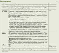
Table 2 lists procedures for assessing well integrity of the casing cement.1
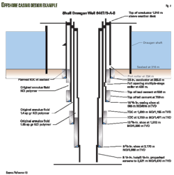
Fig. 2 illustrates an offshore well completion in which the intermediate casing has cement 212 m above surface casing.13 Each intermediate casing string has cement from the shoe to a point at least 600 ft above the shoe.
This well has cement from the shoe up to a point at least 600 ft above the shallowest productive horizon or to a point a least 200 ft about the shoe of the next shallower previously cemented casing string if any productive horizon is open to the wellbore above the casing shoe.13
Production casing varies from 41⁄2 to 95⁄8 in. in diameter and typical procedures require cement far enough above the producing formations to provide additional support for subsurface equipment and to prevent casing buckling.
If the design requires cement for the intermediate or production casings, there should be enough cement to provide annular fill up from the surface casing shoe to 200 ft above the trona interval in a well.
Another typical requirement is that all casing annuli reaching the production zones should have cement for 200 ft or more above the highest producing zone and the casing should be centralized throughout the cemented interval.15
Cementing of the producing string typically is with a pump and plug method or another method approved by regulators. The cement should be sufficient to fill the annular space to the surface or to a point at least 600 ft above the shoe. If any productive horizon is open to the wellbore above the casing shoe, the cement should seal off all such possible productive horizons.14
The production casing cement should cover or isolate all zones that contain hydrocarbons or have a calculated volume sufficient to fill the annular space at least 500 ft above the uppermost producible hydrocarbon zone.15
The intermediate and production casing cement should cover or isolate all hydrocarbons, water aquifers, lost-circulation or zones of significant porosity and permeability, beds containing priority minerals, and abnormal pressure intervals.14
Fig. 2 shows 185⁄8-in. casing cemented 212 m above the shoe.13
One issue that may arise is the location of the top of cement for the 95⁄8-in. casing. In normal wells, the TOC typically is above the previous casing shoe with fluid trapped in the annulus above the TOC.
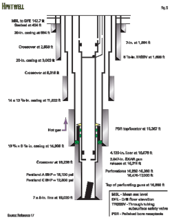
In high-temperature, high pressure wells, hot mud passing up the drill pipe-casing annulus can heat fluid in the casing-casing annulus, causing the mud to expand. If the pressure cannot escape, the pressure can burst or collapse the casing. For this reason, in HTTP wells the TOC for 95⁄8-in. casing may be below the 133⁄8-in. shoe to allow annular pressure to dissipate into the formation.16
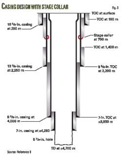
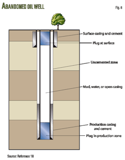
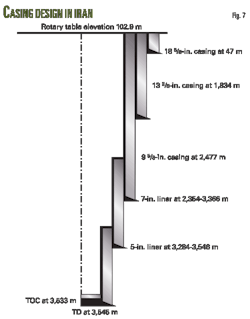
Figs. 1-6 show typical well completions1 9 13 17-19 and Fig. 7 shows a typical well completion in Iran with 185⁄8, 133⁄8, and 95⁄8-in. casing. In Iran, all the casing string annuli have cement to surface with the liner annuli cement tied into the previous string.
Well integrity test
Cement casing tests at the beginning of each well section ensure the integrity of the well throughout its life-cycle. Although cement bond logging predominantly fulfill these testing requirement, well integrity test also must not be neglected.
Logging tools are currently the state-of-the-art method for determining the presence of cement behind casing, fluid flow in the wellbore, and other well construction parameters. But they are not a direct measurement. They are, in practice, a sophisticated form of remote sensing capable of providing adequate information required by the regulations to ensure proper well construction.
A leak-off test at the beginning of each well section after the casing has been cemented tests both the integrity of the cement seal and determines the fracture gradient below the casing shoe. In general, these tests involve closing in the well at the surface or subsurface with the blowout preventer after drilling out the casing shoe and slowly pumping drilling fluid into the wellbore at a constant rate (typically 0.3 to 0.5 bbl/min). The pumping causes the pressure in the entire hydraulic system to increase.
The unsteady nature of surface pressure data can lead to errors in leak-off test estimates of the fracture gradient. The driller needs an accurate measurement of fracture gradient to determine the ability of the formation and casing cement to support the drilling fluid pressure during the next hole section.
The use of stable and accurate downhole annular pressure measurements helps makes drilling ahead a more exact and safer process.20 To ensure the integrity of the surface casing seat, the drilling program should specify leak-off tests.9
Another test is the casing shoe test of the formation directly below a casing shoe. The test typically is run soon after drilling resumes and after the settting of an intermediate casing string. The test determines the maximum pressures that may be safely applied without risk of formation breakdown.
The test results help in determining the design of the mud program for the subsequent hole section and for setting safe limits on casing shut-in.21
After the cement has set and before drilling the plug, drillers typically test the casing to a maximum 1,500 psi. A pressure drop of 10% in 30 min will indicate that the casing cement is inadequate and should be repaired and retested.15
Associated problems
With a high cement column, the casing design should give consideration to production operations that will affect the temperature of the production casing and impose additional thermal stresses. Annulus thermal expansion can cause production casing to collapse when the cement top is in the intermediate casing.
The loads on a production casing are, therefore, different from those imposed during drilling. Access to these annuli could in turn provide a means of applying backup pressure to a casing string, thus reducing the net burst pressure being exerted on that particular string. This feature is not always possible if the annulus is either cemented to the surface or not cemented into the previous casing shoe.9
Radial expansion at the cement-casing interface occurs due to increased pressure in the casing. This creates a stress that compresses the cement rapidly and eventually induces tensile tangential stress in the cement.
A crack may initiate at the casing cement interface when this tangential stress reaches the tensile strength of the cement—which may be close to zero if shrinkage induced cracks already exist. Long-term cement durability is important if a well is to remain safe throughout its life time.
During its active life, a cemented annulus may be subjected to wide variations of temperature and stress from pressure testing, workover operations, and variations in producing conditions (Figs. 8 and 9).22
Any primary cementing deficiencies tend to affect long-term isolation performance. Wide fluctuations in downhole pressure and temperature can undermine cement integrity or cause debonding.
Tectonic stresses also can fracture set cement regardless of the cause. Loss of cement integrity can result in fluid migration, impairment of zonal isolation or casing collapse, even when the well has high-quality cement that was placed properly and initially provided a good seal.23
Acknowledgment
The authors thank NIOC and PUT for permission to publish this article.
References
1. NORSOK Standard D-010, Revision 3, The Norwegian Oil Industry Association and Federation of Norwegian Manufacturing Industries, August 2004.
2. Conrad, K.M., "Well Integrity Management System (WIMS)-A Systematic Way of Describing the Actual and Historic Integrity Status of Operational Wells," Paper No. SPE 110347, SPE Conference, Anaheim, Nov. 11-14, 2007.
3. Prentice, C., Well Integrity Considerations, Halliburton, 2007.
4. Drilling Engineering, Baker Hughes INTEQ, December 1995.
5. IADC Drilling Manual, International Association of Drilling Contractors, 2000.
6. The Alaska Resource Center, Title 20, Miscellaneous Boards and Commissions, Chapter 25. Mental Health Trust Authority, Section 30. Casing and cementing, 20 AAC 25.030. Casing and cementing.
7. Drilling & Well Operations, D-010 Revision 2, The Norwegian Oil Industry Association and Federation of Norwegian Manufacturing Industries, December 1998.
8. Rahman, S.S., and Chilingrain, G.V., Casing design theory and practice, Elsevier, 1995.
9. Casing Design Manual, ENI, June 1999.
10. Canadian Legal Information Institute, Oil and Gas Conservation Regulations, P.E.I. Reg. EC170/74, R.S.P.E.I. 1988, c. O-5.
11. Little Snake RMP Draft Environmental Impact Statement, Resource Management Plan, Appendix H, Oil and Gas Operations, January 2007.
12. BOP Classification System for Onshore Newfoundland and Labrador, Interpretation Note, Issued Under The Petroleum Drilling Regulations (CNR 1150/96), Government of Newfoundland and Labrador, Department of Natural Resources, December 2004.
13. Casing Design—Review of Design Methodology (Shells casing design procedures), Review performed for NPD at Norske Shell, Rock-Well Consultants, November 2003.
14. Drilling and Operating Practices, Home Rule R649-3j, UTA Division of Administrative Rules, January, 2008.
15. General Drilling Rules, Chapter 3, Section 22, Wyoming Oil and Gas Conservation Commission.
16. Texas Administrative Code, Title 16, Part 1, Chapter HA 3, Rule §3.5, Application To Drill, Deepen, Reenter, or Plug Back.
17. Georgia Environmental Protection Division, 391-3-13 oil and gas and deep drilling.
18. Adamson, K., et al., "Drilling and Testing Hot, High-Pressure Wells," Oilfield Review, April-July 1993.
19. Dobson, D., Well Integrity—The UK Experience, Health and Safety Executive, 2005.
20. Duguid, A., CO2 Well Integrity and Wellbore Monitoring, Schlumberger, October 2007.
21. Khandka, R.K., Leakage behind Casing, Norwegian Agency for Development Cooperation, June 2007.
22. Aldred, W., et al., "Using Downhole Annular Pressure measurement to Improve Drilling Performance," Oilfield Review, Spring 1996.
23. Casing Shoe Test, Schlumberger oil field glossary.
24. Bonett, A., and Pafinits, D., "Getting to the road of gas migration," Oilfield Review, Spring 1996.
25. Barclay, I., et al., "The Beginning of the End—A Review of Abandonment and Decommissioning Practices," Oilfield Review, Winter 2001-02.
The authors
More Oil & Gas Journal Current Issue Articles
More Oil & Gas Journal Archives Issue Articles
View Oil and Gas Articles on PennEnergy.com
