CO2 INJECTION—1: Restaged CO2 compressors, new pumps remove bottleneck at Weyburn
The restaging of CO2 compressors and installation of injection pumps removed the bottleneck caused by the lack of reinjection compression capacity for the produced recycled gas at EnCana Corp.'s Weyburn Saskatchewan oil battery. The battery reinjects dense-phase CO2 for enhancing oil recovery.
The reinjection process entails separating produced gas from the oil, compressing the gas, and then recycling it into the reservoir together with CO2 from the North Dakota's Great Plains Synfuels Plant.
EnCana lead facilities engineer Blair Eddy developed a detailed plan for adding capacity that involved pumping the dense-phase recycled gas.
EnCana Weyburn engaged Falcon EDF Ltd. to perform the detailed engineering to implement Blair's plan and work under his direction.
This first of a two-part series describes the design work for the projects. The second part will cover the detailed engineering.
Weyburn battery
The Weyburn battery, built in the mid 1950s, produced 10,000 b/d during its peak primary recovery phase. Secondary recovery with field-water injection commenced in the 1960s.
In 1997, EnCana and partners signed a carbon-dioxide supply agreement with Dakota Gasification Co. (DGC). DGC is a wholly owned subsidiary of Basin Electric and Power Cooperative of Bismarck, ND, and owns and operates the Great Plains Synfuels Plant.
A 323 km, 16-in. pipeline from Beulah ND conveys the CO2 to Weyburn, Sask. Current CO2 delivery to Weyburn is 125 MMscfd.
Oil production at the battery has increased to 29,000 b/d and Encana expects production to continue to increase as it refines the injection strategy.
The existing reciprocating K-701-1/2 compressors, capable of compressing 25 MMscfd each, were a bottleneck. Due to problems in bringing on additional compression as quickly as required, EnCana management directed its lead facility engineer Eddy to fast track an interim alternative of recylindering existing compression with dense-phase CO2 pumping after the restaged compression.
Recycle compressions
Existing compression consisted of two Cooper W-76 Frame, 6,000 hp, four-stage electrically driven compressors. Each compressor can handle 25 MMscfd (882,000 cu m/day). Inlet suction pressure was 1,000 kPa and discharge pressure was 15,300 kPa.
The stages consisted of two 17-in. cylinders on the first stage, two 11.5-in. cylinders on the second stage, one 9-in. cylinder on the third stage, and one 8-in. cylinder on the fourth stage.
The plan was to fast track restaging the compressor. The change from four stages to three stages would increase throughput. A centrifugal multistage pump would give the final boost.
The advantage of this plan was that the cylinders required for restaging compression and the pumps had shorter delivery times than installation of a new compressor.
The recylindered compression configuration was:
• Stage 1: two 17-in. new cylinders with a higher than existing maximum working pressure.
• Stage 2: two 11.5-in. existing cylinders.
• Stage 3: two 9-in. new cylinders.
The pumps chosen were Schlumberger Reda 64-stage J350N 675 series multistage horizontal centrifugal pump. The initial pump motor selected was a variable-frequency drive controlled, 400-hp motor; however, once the pump ran, the motor's available horsepower was too low.
The required flow rate of the 82% CO2, 0.6 specific gravity, dense-phase recycle gas required 520 hp. Subsequently, the pump required upgrading to a 600-hp motor.
To ensure pump redundancy and ample capacity, the design required installation of two pumps per compressor train. A programmable-logic controller controlled the pumps. One pump operates at 100% capacity, while pump suction pressure controls the other one that had a VFD drive. Thus, the second pump ensures a uniform compressor throughput.
In addition, the design included installation of heat exchangers to avoid summer 43° C. gas off the third-stage compression from bottlenecking the Reda pump. Note that dense-phase CO2 is very sensitive to temperature. As temperature increases above 25° C., the specific gravity decreases rapidly, thereby lowering the pump's throughput volume. As the specific gravity increases, the throughput increases and the horsepower required increases also.
Fig. 1 shows the pump performance curves for recycled gas with a 0.65 specific gravity, 82% CO2 at 25° C.
Fig. 2 shows a 3D Autocad drawing of the piping with the newly installed skids.
Design basis
The properties of the crude oil, based on the CoreLab PCP Weyburn composite analysis Apr. 29-May 13, 1992, were:
• Dark brown color.
• 27.6° gravity at 15° C.
• 889 kg/cu m at 15° C. absolute density.
• +4° C. pour point.
Table 1 lists the distillation cuts; Table 2 shows the oil viscosity at different temperatures.
Based on the latest information given by EnCana for the debottlenecking study, the gas has a 1.46 sp gr. (42.4 molecular weight) with current and future gas compositions as shown in Table 3.
The design work included the simulation to two cases. The first case was for low flow of 35 MMscfd (991,000 cu m/day)and low 82% CO2. The second was for high flow of 45 MMscfd (1.27 million cu m/day) and high 93% CO2.
Table 4 shows the new approximate operating conditions for the three-stage existing recycle compressors for the two operating cases (low and high).
The existing cooler capacities were:
• 7.24 MMbtu/hr for first stage (old second stage).
• 6.21 MMbtu/hr for second stage (old third stage).
• 9.68 MMbtu/hr for third stage (old fourth stage).
The maximum case cannot reach 45 MMscfd due to cooler limitations.
The projected new third-stage cooler duty required for the high-flow case was 11.1 MMbtu/hr. Therefore, the restaged compressor could not deliver.
Total driver power of the K-701-1/2 compressors was 6,000 hp each.
Injection pumps
The pump design conditions for the two 400 hp (initial motor size) Schlumberger-Reda 64-stage, 1,100 psi boost pressure pumps were:
• 2,300 cu m/day liquid design flow.
• 2,700 cu m/day maximum liquid flow.
• 7,585-8,620 kPa-a at 43° C. inlet conditions.
• 15,300 kPa-a discharge pressure.
• 3,570 rpm, VFD compatible pump speed.
• Dense-phase CO2/H2S/HC (see gas analysis) internal material.
• TEFC-XP motor.
An injection recycle gas pump skid would house the two multistage pumps.
Instrument air from the existing battery air compressors provided instrument air for all pneumatic devices. The design included a new remote-rack PLC for controlling the new Reda pumps. The new PLC provided local overall process control.
Power for the pumps was from the existing 4,160-v line. A new 750-kva transformer reduced the voltage to 480 v.
A spare area in the main master control center building housed the switchgear and fuse for the new pump feeders. The design used the existing flare for blowdown and pressure safety valve discharge because the gas is sour. The process directed all equipment purges, PSVs, and blowdown valves to flare.
The skid also housed all critical instruments such as vibration switches, gas detection, and pressure transmitters.
Material balance
Based on compressor discharge conditions, it was evident from the pump curves and the phase envelopes for the different CO2 concentrations of the recycled gas that several conditions would govern the pump suction.
Fig. 3 shows the phase envelopes for recycled gas concentrations varying from 76-100% CO2. The dense-phase critical point pressure varies from 8,200 kPa for 76% gas to 5,800 kPa for 100% CO2 gas. Hence, the process ensures a dense-phase gas at the existing 82% CO2 concentration and a Reda pump suction pressure of 8,458 kPa-g. This pressure is greater than the 7,800 kPa critical point pressure for 82% CO2 gas.
Fig. 4 shows the pump curve provided for the REDA HPS 675 series 0.65 sp gr dense-phase CO2. For 82% CO2 gas, the required pump's inlet pressure temperature is 24° C. at 8,458 kPa-g. The pump curves provided under predicted horsepower and over predicted flow rate.
After installation, the running of the pumps provided actual flow rates, pressures, and temperatures.
The x and y axes of Fig. 1 compare the actual operating parameters with the curve values. Note that the actual capacities are 2,400 liquid cu m/day vs. 2,700 liquid cu m/day and 2,700 liquid cu m/d vs. 3,000 liquid cu m/day. The 2,400 liquid cu m/day is equivalent to 35 MMscfd of gas and the 2,700 liquid cu m/day is equivalent to 39 MMscfd gas.
The actual curve horsepowers were 520 and 598 for the 2,400 and 2,700 liquid cu m/day flow rates, respectively.
Because of the curve under predicting the horsepower and flow rates, EnCana decided to install two pumps per train (a total of four pumps) with 600-hp motors on each.
As discussed previously EnCana also decided to ensure a constant pump temperature in the summer. It decided to install heat exchangers as soon as possible.
To minimize size constraints in the battery, it selected a compact printed-circuit exchanger. The overall (flange to flange in-out) dimensions of these exchangers were 45-in. overall width and 76-in. overall length
Fig. 4 shows the exchangers installed. An equivalent shell and tube exchanger would have required two stacked exchangers each consisting of two 1,219 mm (4 ft) diameter by 13,176 mm (45 ft) long units (2 by 2 stacked exchanger units).
Fig. 5 shows the heat-exchanger profile. It assumes summer conditions with the DGC pipeline exchanger gas inlet temperature of 5° C. and the K-701 compressor cooler third-stage outlet at 43° C. into the exchanger.
The process required installation of inlet strainers upstream of both exchanger inlets because the exchangers are susceptible to fouling. Inspection of recycled and DGC gases shows them to be extremely dirty on start-up. The heat-exchanger strainers were worth the investment but were extremely time consuming to depressure and clean.
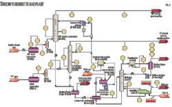
Fig. 6 shows a single-train process flow diagram. The material balance for the summer conditions and a liquid flow rate of 2,700 liquid cu m/day or 39 MMscfd of gas equivalent dense-phase CO2 was one of the key conditions evaluated. The main data for this material balance are:
• Dense-phase recycled gas with 82% CO2 flowing at 39.3 MMscfd at an ambient 43° C.
• DGC heat-exchanger gas flow at 42 MMscfd.
• An 8,460 kPa-g at 43° C. compressor third-stage discharge pressure.
The PFD-material balance shows the three-stage compressor and coolers, the Heatric printed-circuit heat exchanger, and the Schlumberger REDA booster-pump stream data. The stream table shows the critical parameters for ensuring that the design meets all required process conditions.
One can check any condition of the plant on the PFD material balance; for example the Reda horsepower is 594 (stream hp-reda701). The most important stream is Stream 17, which shows the process conditions before the pump suction.
Stream 17 key parameters are:
• 39.3 MMscfd dense phase flow, mostly CO2.
• 8,548 kPa-g at 24° C. pump inlet pressure.
• 0.655 kg/cu m mass density.
From the above simulation results, it is evident that any slight fluctuation in the temperature (specific gravity) changes the throughput through the pumps. To meet the 35-40 MMscfd (2,400-2,700 liquid cu m/day) throughput, the specific gravity must be 0.65 or the dense phase fluid into the pump must be below 24° C. with at least a 600-hp pump motor driver.
Economics, schedule
The design work modified the project as a whole several times to ensure that the motors had enough horsepower and the summer month's weather would not overheat the gas into the pump suction.
The final installed cost for the equipment and materials was $4,893,000 broken down as follows:
• $2,375,000 for four pumps (piped and wired) on fully enclosed skid.
• $660,000 for two sets of new compressor cylinders.
• $593,000 for two Heatric heat exchangers.
• $244,000 for electrical and instrument equipment.
• $1,321,000 for pipe valves, fittings, control valves, structural steel, and insulation.
The construction cost was $3,606,000. This included $2,637,000 for the mechanical and civil installation work and $969,000 for the electrical instrumentation work.
Total project cost was $9.928 million.
To understand the economic advantage of this project, following is a comparison of the cost of new compression vs. the upgrade.
An installed cost of a reciprocal 4,000-hp compressor with a 25 MMscfd throughput is $26 million compared with the $10 million cost of a three-stage, one-train K701s with REDA rated for a 39 MMsfd throughput.
The 4,000 hp compressor costs were from a canceled project fully scoped and bid for the Weyburn plant last year.
Total production increase for the two trains was 28 MMscfd (2 × (39-25)).
Addition of the dense-phase pumps and restaging compression added 28 MMscfd for a $10 million investment vs. the $26 million of compression to realize a 25 MMscfd gain. This translates to $0.36 million/MMscfd for compressor restaging-pumps vs. $0.96 million/MMscfd for reciprocating compression.
Schedule
Fig. 7 shows the simplified project schedule, derived from the final project completion schedule as recorded after start-up.
In spite of all the additions, it took 9 months to complete the project as scheduled.
The schedule included the following long lead items:
• Design and engineering of process equipment, skids, in plant piping modifications, electrical upgrades, control philosophy-design, and turnaround electrical-piping tie-ins.
• Delivery of all long delivery equipment, such as cylinders, pumps, heat exchangers, VFD, transformers, and upgraded motors.
• Installing equipment in skids.
• Pipe racks with piping and cable in cable trays.
• PLC program.
• Plant turnaround.
• Final tie-ins.=
The author
More Oil & Gas JOurnal Current Issue Articles
More Oil & Gas Journal Archives Issue Articles
View Oil and Gas Articles on PennEnergy.com
