LOW CO2 SLIP—1: Canadian experience shows actual operations needed to guide choice of amine simulator
Experience in 2008 with various marketed process simulators modeling Suncor’s Simonette gas plant showed that predicted results differed widely from actual operating conditions.
Choosing an amine simulator must accordingly be done carefully and the results adjusted on the basis of known operating data; otherwise the simulated values may prove questionable. In the design of a new amine system, reliance on numbers generated from a process simulator is not recommended no matter what previous successful results were obtained because even slight variations of the operating conditions and feed concentrations may cause widely varying results.
Therefore, an expert knowledge of amine systems with experience on similar, successful, and working installations provides the best reference for whether a system will behave as intended. Also, establishing a close working relationship with an amine supplier that will guarantee performance results of the amine in any contemplated gas-sweetening installation may help to circumvent problems such as the low CO2 slip experienced at the Simonette plant.
That plant, while designed for a CO2 slip application using methyldiethanolamine (MDEA) and operating at about 1,000 psig, was experiencing low levels of CO2 slip. The plant’s inlet acid-gas concentrations were 2-3% H2S and CO2 in varying proportions. The downstream stripped acid gas from the regenerator, subsequently flowing to a Claus sulfur unit, created operating problems due to the low-btu content of the acid-gas stream.
After a comprehensive review of available literature,1-11 process modeling work was undertaken to study various parameter changes potentially affecting CO2 slip, using actual plant mechanical data on actual tower diameters, tray spacing, active areas, weir heights, and tray types. Output from several process simulators, including equilibrium stage and mass transfer rate-based models, was compared with actual plant equipment and conditions in order to study the effects of varying column mechanical dimensions, amine circulation rate, inlet gas and lean-amine feed temperatures, and blends of amines.
The modeled results from all the simulators used did not compare favorably with the actual CO2 plant slip, measured to be about 0.2%. While searching for a solution to optimize CO2 slip by varying key parameters, the investigation turned to focusing on diethanolamine (DEA) contamination. It was coincidentally found that other Alberta high-pressure sweetening plants exhibited decreased CO2 slippage as a result of blended amines, primarily with the introduction of small amounts of DEA. To date, there has been no comprehensive explanation of why Simonette and other installations suffer from low CO2 slip.
DEA contamination may be hard to avoid in the operating life of the high-pressure MDEA absorber system and, once present, may not be completely and adequately expunged to allow required CO2 slip rates. An additive to negate the effects may be the only viable recourse. Further research may provide the definitive answers in the future.
This two-part series presents this experience together with the modeling results. It also presents a theoretical model of probable mechanisms for limited CO2 slip that may help explain the effects of mixed amines at high pressure for CO2 slip and MDEA applications.
The concluding article will focus on the actual simulation output comparisons and selected parameter sensitivities. In addition, a nontraditional contacting three-stage static mixer design employing very short clear liquid residence times will be introduced.
Modeling results comparing the addition of DEA will be shown, and other high-pressure MDEA plants exhibiting DEA contamination will be reviewed. A theoretical model proposing a novel reaction method will be shown as well as a discussion of the proprietary nature of amines.
Cabin Creek
Suncor’s 85-MMscfd Simonette sour-gas plant in northwestern Alberta processes sour inlet gas from low and high-pressure feeds, combines sweet gas from various other pipelines, and provides dewpoint control and compression for export through a high-pressure sales gas line.
The plant takes a high-pressure feed originating from Cabin Creek pipeline and processes the gas in a 2006 plant expansion high-pressure amine contactor, C-520. Although the plant is designed to use MDEA, a selective amine used for its ability to slip CO2, the treated gas is consistently low in CO2 content with little or no slip measured. The near total absorbed and subsequently stripped CO2 causes problems for operation of the downstream Claus plant, where the acid-gas feed is low in heat content, requiring supplemental firing.
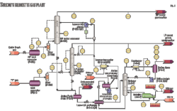
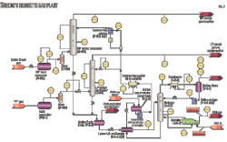
Cabin Creek inlet gas flows through HP inlet separator V-500 through filter V-510 and into the 20 tray high-pressure amine contactor C-520 operating at about 1,000 psig (68.9 barg; Fig. 1). Low-pressure inlet “Y” gas flows through inlet separator V-2-1, through filter V-200, and into the 27-tray low-pressure amine contactor C-2-1 operating at around 260 psig.
Rich amine from both C-520 and C-2-1 is gathered into amine flash drum V-2-5, the offgas flowing to a small packed column, which sweetens the gas used in the fuel gas system (not shown in Fig. 1).
The 75 psig back pressure on the drum is indirectly controlled downstream of the fuel gas contactor (not shown). V-2-5’s liquid level is controlled through LV-2401, cross exchanged with lean bottoms in the lean-rich exchanger E-2-4 A/B and processed by stripper C-2-2.
That stripper, a 17-stage distillation column operating with a 31-psia bottoms pressure is configured with reboiler E-2-7 using 60/40 ethylene glycol as heat medium and an aerial cooler condenser E-2-8. Condensed liquid flows through the reflux drum V-2-7 and reflux pumps P-2-2A/B, while offgas from the reflux condenser is directed to a Claus plant downstream.
Lean amine from the lean-rich exchanger flows into the amine accumulator surge tank and through to the lean amine charge pumps P-2-1 A/B, supplying the bulk flow of amine; about 140 gpm to the LP amine contactor at about 260 psig and acting as a booster to the lean-amine pumps P-525 A/B.
The lean-amine (aerial) cooler E-2-6 A/B/C reduces the temperature of the bulk flow before the stream split. A high-pressure lean amine supply delivered by the lean-amine Pumps P-525 A/B increases the 325 gpm lean-amine supply pressure to HP Contactor C-520.
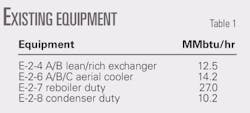
Table 1 shows specific duties of the existing heat-exchange equipment, and Table 2 provides details of the distillation column.
Attempted solutions
Low CO2 slippage can normally be compensated for by lowering the lean-amine feed point. Simonette lean-amine feeds at Trays 18 and 16 on C-520 were tried. While some slip improvement was made with Tray 16, it was less than 0.5% and at the expense of a higher H2S specification in the treated gas.
During preliminary discussions between Simonette plant personnel and Jacobs Engineering team in June 2009, it was reported that interstage cooling had been experimented with, but the results were not made accessible. Although details about implementation are unknown, it was reported that increased slip was not realized after introduction of interstage cooling.
Reboiler duties approaching the design capability had been tried, increasing the stripping by offering a low acid-gas-to-amine ratio. Lab testing indicated near 0.005 mol acid gas to mol amine.12 13 According to available literature, adequate stripping is apparently being achieved and follows the current amine supplier’s recommendations.
By nature, the inlet feed gas is at 4-8° C. (40-46° F.) throughout the year. Lean amine is cooled in an aerial cooler exposed to fairly cool ambients during most of the year. At the time of the test July 3, 2008 just after midnight, the lean-amine temperature was 83.5° F.).
Operations
Based on a normal differential pressure monitored across the columns, the plant did not exhibit any foaming. There was some indication that the lean-rich exchanger was undersized, but at the flow rates exhibited, not deemed a significant problem. Additional cooling could be made up downstream at the lean (aerial) cooler. As mentioned, the lean-amine acid gas loading seemed reasonable and the plant was able to make H2S spec sales gas.
Although the amine feed point could be dropped a few trays, the CO2 pickup did not abate enough to warrant driving the reboiler harder for a leaner amine. It was initially speculated that the column was oversized, but it is generally viewed to be capable of slipping more CO2 than the near zero being experienced.
System modifications
Focusing on areas that would provide an easy solution were questions about whether decreasing the lean-amine feed temperature would be able to solve the slippage. Introduction of a precocurrent contact static mixer was posed as perhaps being beneficial. Decreasing the weir height (currently at about 3 in.) or the active tray area to reduce the contact time was proposed as to whether this could increase CO2 slippage. Modeling the system with a process simulator could possibly answer these questions.
MDEA amine systems
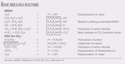
Selectivity in absorbing H2S while slipping CO2 can be normally achieved by use of a tertiary amine such as MDEA due to differences in kinetic rates. In MDEA systems, H2S reacts quickly with the amine, while CO2 is relatively slower allowing it to be “slipped.”
CO2 as a Lewis-type acid gas cannot react directly with MDEA, instead needing first to form carbonic acid (H2CO3) by combining with water. Carbonic acid then deprotonates, forming bicarbonate, while the proton is transferred to the basic amine and ultimately yields an amine bicarbonate.
This reversible reaction is kinetically dominated by the carbonic acid formation and therefore quite slow, especially at low temperatures. The MDEA-carbonate is not heat stable. At higher temperatures, the volatility of the CO2 increases, leading to lower equilibrium loadings of the MDEA solution with CO2 .
In contrast, H2S converts immediately to sulfide (and bisulfide) ions via a simple instantaneous deprotonation reaction when it dissolves into an aqueous amine solution. Although this reaction is fast, it is also highly reversible and depends on solvent alkalinity. The reaction generates heat.
In design of a system to slip CO2 , minimizing the length of time the gas mixture and solvent become intimate can promote H2S to be absorbed more rapidly relative to CO2 . Driving the absorption of H2S into solution is the concentration difference between H2S in the gas phase and the absence of the unreacted form of H2S in the liquid.
CO2 will react with MDEA and, as discussed, at a slower rate that partially depends on temperature. Note that when H2S reacts (quickly), the temperature of the solution increases as a result, making absorption of CO2 easier. As more CO2 (and H2S) are absorbed, the alkalinity of the solution decreases, making absorption of H2S harder by removing the ability to keep all H2S in its anionic form with MDEA in a protonated form.
As a result, H2S will eventually start to desorb when the protonated MDEA associated with the HS– and S= ions starts to deprotonate (see accompanying box below).
Alternately, CO2 will continue to react and absorb until the equilibrium loadings of H2S and CO2 are reached. Unfortunately, the reaction equilibrium favors keeping the CO2 in solution and aides itself by actually releasing absorbed H2S. Clearly, this is a complex system.
Making the system even more complex is absorption diffusional effects for both the H2S and CO2 gases. Expanding on the ability of H2S and CO2 to be captured in the liquid and gas phases, the diffusional resistance for CO2 occurs primarily in the liquid phase, while the resistance for H2S occurs in the gas phase. As such, column internals can theoretically be configured to maximize mass transfer of an acid gas in one phase compared with the other, altering the relative absorption rates and maximizing CO2 slip.
Promoting CO2 slip
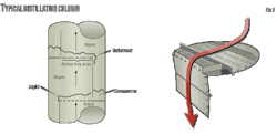
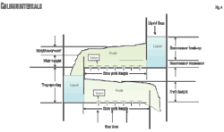
The vapor passing up through the column can be accommodated through the tray deck by various means. C-520 uses valve trays (in contrast to bubble cap or sieve trays). In valve trays, perforations are covered by liftable caps. Vapor flows lift the caps, thus self-creating a flow area for the passage of vapor. The lifting cap directs the vapor to flow horizontally into the liquid, thus providing better mixing than is possible, for example, in sieve trays (Figs. 2-4).
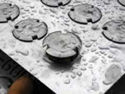
This is a typical valve tray (Fig. 3).
A popular way of interpreting a system of good mechanical design, accounting for maximizing H2S pickup while allowing CO2 to slip, is by clear liquid residence time (CLRT).16 A system designed to pick up H2S while slipping CO2 is partly accomplished by a mechanical design allowing short liquid residence time. A generally accepted amount of CLRT for CO2 slip applications is 2 sec (see Equation 1 in accompanying box at top of this page).17
One model that can be used to calculate liquid height-over-weir is the Francis weir formula (Equation 2). Bolles further published a correction factor used for segmental downcomers.18 Note that the relationship in Equation 2 is without the weir constriction factor effect.
Further work that estimated froth gravity, however, may not be totally accurate in its depiction of CLRT since being applicable to sieve trays.19 A relationship was proposed by Colwell, also for predicting froth density on sieve trays, uses an iterative method.20 Kister writes that development of a clear liquid height correlation for valve trays is inhibited by the measurement of the clear liquid height.21
As Equation 1 shows, in theory, CLRT is indirectly proportional to the total supplied amine solution flow rate and directly proportional to tray surface area and froth depth. It would appear that decreasing the CLRT by increasing the flow rate would not subsequently increase CO2 slip as found in earlier experience from the Waveland plant in Mississippi.22 This may be as a result of the increased circulation rate holding the temperature cooler in the column.
In design of a high CO2 slip ratio, it is traditionally thought important to minimize the CLRT by mechanical means. This can be accomplished in different ways or in combination, such as keeping the active area low, reducing the weir height, or keeping the reacting amine flow high.
A particular note can be made with respect to froth height. It is generally believed that the gravity of the froth changes continuously as the flowing gas, entering from the bottom of the tray, is entrained within the liquid. A density gradient further complicates calculation of froth density.
Process simulation
To answer whether plant simulation could offer any insights for improvements in CO2 slip, operators modeled the system using actual column dimensions with commercially available process simulators specifically made for amine applications. Flow rates and field modifiable parameters were varied with effects noted.
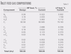
• HP inlet feed composition. The initial design was based on an inlet feed composition 2.23% H2S and accompanying CO2 concentration of 3.19%. Feed compositions reported by gas chromatograph on July 3, 2008, downstream of the Cabin Creek inlet separator V-500 were 3.63% H2S and 2.03% CO2. Table 3 summarizes feed compositions including the inlet fed to the low-pressure amine contactor.
• Feed temperature, pressure. The original plant was designed for an inlet temperature and pressure of 1,000 psig at 4.4° C. Current pressure and temperature levels are recorded as within that range, falling to 923.8 psig and a slight increase to 7° C. on July 3, 2008.
• Feed flow rate. The original inlet flow rate was designed for 85 MMscfd. Current flow rates range around 71 MMscfd. Table 4 below lists the flows encountered on July 3, 2008, for the high-pressure and low-pressure amine contactors. Flow values appeared to be constant over a 12-hr period given the intervals reported.
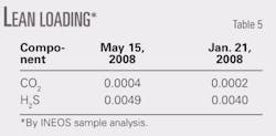
• Lean-amine flow rates. Flow rates were described previously. Sample analysis by INEOS indicated the acid components to amine mol/mol amounts in Table 5.
• Lean-amine loading. Lean loading (mol acid gas to mol MDEA) had been analyzed the preceding May and by an earlier sample taken in January.12 13 As these samples represent an average stripping level in day-to-day operations, this is in fairly good agreement with recommended values.23
Lean-amine loadings, being a function of the reboiler duty in the simulations, were specified or adjusted in order to compare with sampled data.
• Lean-amine composition. Table 6 shows a small amount of DEA that, over a period of 4 months, appears increasing. The plant has upstream chemical addition that was at the time in 2008 supplied by nonblanketed storage tanks, thought to be the source of oxygen, which may have led to MDEA degradation into the DEA component. Currently, work is under way to identify the sources and eliminate air infiltration. Further discussion of DEA’s role in CO2 pickup appears presently.
• Rich-amine loading. Typical rich loadings for amine systems using MDEA are 0.2-0.55.23 It is worthwhile to note that the typical values cited are general design constraints representing acceptable concentrations with respect to flowing velocities of typical line sizes.
Real values are best correlated to actual resulting velocities in selected line and equipment flow paths that, beyond certain acceptable figures, would have the effect of stripping oxide layers, resulting in accelerated corrosion.
• Mechanical equipment parameters have already been stated.
Preliminary simulation results
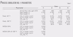
Before actual gas compositions or plant operating parameters could be obtained, earlier work involved changing some parameters to monitor the effects on CO2 slip using the original design case conditions (Table 4). Parameters were selected based on field modifiable items or whether inlet feed temperatures had the effect of invoking significant changes.
Simulator No. 1 initially employed is a popular, amine-specific simulator used by many in the industry. Weir height, amine circulation rate, a combination of circulation rate and weir height, inlet feed temperature, amine solution strength, and a combination of inlet feed temperature and amine solution strength were experimented with for the high-pressure amine contactor handling the majority of the treated gas.
The particular simulator used did not allow free configuration of the components such as modeling of the additional low pressure amine contactor or combining the rich amine into a common stripper. A straight 50 wt % MDEA solution was applied.
Table 7 suggests that decreasing the flow rate may improve the CO2 slip, contrary to expectations derived from Equation 1 in relation to CLRT. Directionally, CO2 slip is shown to improve when the weir height (exaggerated) is decreased.
Using a hotter feed also seemed to increase slip, contrary to what theory would lead one to believe without looking deeper into actual column temperature bulge, which could indicate release of CO2 from solution greater than 130° C. Decreasing solution strength also increased the slippage. The obtained results did not inspire much trust, given that the plant, operating close to the design point, was not getting similar slip or treated-gas outlet concentrations. Getting total comparative results for all the cases was not pursued.
Simulator comparisons
During the course of the study, many preliminary cases were compiled and compared, yielding highly varied results. It was hard to tell which simulator produced the most reliable values without correlation to existing plant data or from a similar designed amine plant.
Once official plant data became available, specific column parameters as well as the inlet feed compositions were added to the models. Up to this time, a mixture of design conditions and ultimate feed characteristics were used in order to observe which parameters could be changed to increase CO2 slip drastically. No previous results were conclusive because, for example, many of the simulators used were off by a couple orders of magnitude in their predictions of CO2 slip.
• Simulator No. 2 is an amine-specific simulator, with features allowing the use of mixed amines and for modeling of column internals including trayed and packed columns. It offered very good convergence characteristics. While actual trays could be modeled, the process vendor suggested using ideal stages with actual column and tray dimensions.
• Simulator No. 3 is a commonly used simulator specifically designed for amine systems. It allows for mixed amines and modeling of column and tray dimensions. This simulator offered the ability to model some of the heat-stable salts in solution. Convergence ability was slightly poorer than Simulator No. 2 but was very effective after gaining experience with some operating anomalies.
• Simulator No. 4 is a general purpose process simulator that many use for modeling amine systems and was used in the original design of Simonette. It offers some limited blended-amine capability and physical parameter manipulation.
• Simulator No. 5 has recently appeared on the market and offers modeling of blended amine and physical column and tray dimensions.
To reiterate: Simulator No. 1 was not used in the comparison table because it had limited capability in modeling the total Simonette amine system.
While an attempt was made to make an accurate comparison between simulation programs, it was found that common molecular components could not be specified. (Table 6 shows the results of INEOS amine analysis performed on the dates shown, showing some of the heat-stable salts prevalent in the solution.)
Simulator No. 3, for example, allowed many of the heat-stable salts to be input, whereas the others did not include these in the component selection. As such, a complete comparison across the board showing the effects of heat-stable salts could not be made but was included as a comparison case by itself to demonstrate how these components may directionally affect the system’s behavior.
Simulator No. 4 did not allow the addition of sulfates, modeled as a small amount of sulfuric acid in the other simulator cases.
Not all simulators allowed the modeling of actual trays. Simulator No. 2 showed the most accurate values in relation to actual measured plant data but modeled with theoretical stages, that combined with actual column tray dimensional data (weir heights, column diameters, weir lengths/active areas, etc.), as recommended by the process vendor to provide the most accurate results.
Simulated CO2 slip
Simulator No. 3 was adjusted to achieve an acid-gas loading similar to the other cases. Driving the reboiler harder to attain 0.005 acid-gas loading, however, produced much higher reboiler duties than the existing equipment was capable of. Notably, the results indicated less duty was required when balancing the acid-gas component in the sweetened gas, which was brought down to considerably low levels.
All cases except for Simulator No. 2 showed the amount of CO2 slip to be roughly in the range of 25-65%, inconsistent with field results indicating 0.05-0.1%. Discussions with industry spokesmen revealed no reasonable explanation for why the simulation results varied with respect to actual CO2 slip vs. modeled results.
As one amine technical expert put it, by virtue of the specified selective amine used, C-520 would have required 50 trays to account for the experienced CO2 pickup. One amine supplier also speculated that there was no accountable reason why at least 30% slip could be achieved. ✦
References
- Perry, Robert H., Green, Don W., and Maloney, James O., Perry’s Chemical Engineers’ Handbook, 6th Edition, New York: McGraw-Hill, 1997.
- Kohl, Arthur S., and Nielsen, Richard B., Gas Purification 5th Edition, Houston: Gulf Publishing, Houston, 1997.
- Weiland, H., and Dingman, John C., “How to Increase CO2 Slip,” Laurance Reid Gas Conditioning Conference, Norman, Okla., Feb. 25-28, 2001.
- Law, Denny, “New MDEA design in gas plant improves sweetening, reduces CO2,” OGJ, Aug. 29, 1994, p. 83.
- Liebert, Tim, “Distillation feed preheat—is it energy efficient?” Hydrocarbon Processing, October 1993, pp. 37-41.
- Rooney, Peter C., DuPart, Michael S., and Bacon, Thomas R., “The Role of Oxygen in the Degradation of MEA, DGA, DEA, and MDEA,” Laurance Reid Gas Conditioning Conference, Norman, Okla., Mar. 1-4, 1998.
- Daviet, Gilles R., Donnelly, Steven, and Bullin, Jerry, “Dome’s North Caroline Plant Successful Conversion to MDEA,” GPA Annual Convention, New Orleans, Mar. 19-21, 1984.
- Robertson, Kevin, Stern, Lon, Tonjes, Mark, Dreitzler, Lindsay, and Stevens, David, “Increase H2S/CO2 selectivity with Absorber Interstage Cooling,” Laurance Reid Gas Conditioning Conference, Norman, Okla., Feb. 22-25, 2004.
- Thomas, James C., “Improved Selectivity Achieved with UCARSOL Innovator Solvent 111,” Laurance Reid Gas Conditioning Conference, Norman, Okla., Mar. 7-9, 1988.
- Weiland, R.H., Sivasubramanian, M.S., and Dingman, J.C., “Controlling Selectivity, Increasing Slip and Reducing Sulfur,” Laurance Reid Gas Conditioning Conference, Norman Okla., Feb. 23-26, 2003.
- Danmier, Bryan, Roesler, Kevin, and Daughtry, James, “DEA Conversion to MDEA Based Solvent Results in Energy Savings and Increased Treating Capacity at the Energy Transfer LaGrange Gas Plant,” Laurance Reid Gas Conditioning Conference, Norman, Okla., Feb. 26-Mar. 1, 2006.
- INEOS Solvent Analysis, Sample No. 20081132A taken on May 15, 2008.
- INEOS Solvent Analysis, Sample No. 20080459A taken on Jan. 21, 2008.
- Hatcher, Nathan A., Weiland, Ralph H., and Sivasubramanian, M.S., “Are Your Simulation Amines Too Clean?” Laurance Reid Gas Conditioning Conference, Norman, Okla., Feb. 26-Mar. 1, 2006.
- Kent, R.L., and Eisenberg, B., “Better Data for Amine Treating,” Hydrocarbon Processing, February 1976, pp. 87-90.
- BRE Technical Note, Trayed Column Residence Time Calculation.
- MacKenzie, D.H. et al., “Design & Operation of a Selective Sweetening Plant Using MDEA,” Energy Progress, March 1987: pp. 31-36.
- Bolles, W.L., Pet. Refiner, Vol. 25 (1946), No. 613.
- Smith, B.D., Design of Equilibrium Stage Processes, New York: McGraw-Hill, 1963, p. 552. Bolles, William L., and Faire, James R., contributed Chapters 14 and 15.
- Colwell, Charles J., “Clear Liquid Height and Froth Density on Sieve Trays,” Industrial Chemical Process Design Developments, 1981, pp. 298-307.
- Kister, Henry Z., Distillation Design, New York: McGraw-Hill, 1992, p. 320.
- Ammons, H.L., and Sitton, D.M., “Operating Data from a Commercial MDEA Gas Treater,” Laurance Reid Gas Conditioning Conference, Norman, Okla., Mar. 2-4, 1981.
- GPSA Engineering Data Book, 11th Ed., Tulsa: Gas Processors Suppliers Association, 1998, Fig. 21-3, “Approximate guidelines for Amine Processes.”
The authors
