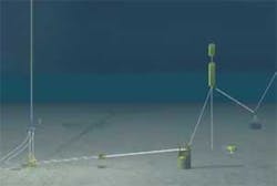
Analyses assessing the possible use of a free-standing hybrid riser (FSHR) as part of an offshore field development export system should both thoroughly address fatigue damage during installation and determine the allowable sea states for deployment. Total damage should consider both installation and operation phases. Buoyancy can (BC) vortex-induced motions (VIM) may also cause fatigue damage and should be investigated.
The first article in this three-part series described the FSHR in detail before examining its design and installed responses (OGJ, Nov. 10, 2008, p. 58). This second article details FSHR in-place fatigue, installation and monitoring, with the concluding article (next week) discussing its integration with the export pipeline.
In-place fatigue
FSHR system and component fatigue-life analyses examining first and second-order motions show damage along the rigid riser components as negligible (in excess of 99,999 years life expectancy), with minimum fatigue life at the top-riser assembly (797 years).
The high first and second-order fatigue lives for FSHR components stem from the flexible jumper’s decoupling of the riser from vessel wave-induced motions. The BC’s depth below the sea surface also reduces direct wave action on the structure.
Total long-term fatigue damage to the FSHR, however, must consider two additional fatigue sources: riser vortex-induced vibrations (VIV) and BC VIM. In-place fatigue damage also must be combined with installation fatigue damage.
Shear7, version 4.4, performed VIV analysis, projecting each current velocity profile both onto the flexible jumper plane (in-plane velocities) and perpendicular to that plane (cross velocities) and considering the angle of the current’s direction with regard to the plane. The out-of-plane damage is the sum of damages due to projected in-plane current velocities, while in-plane damage is the sum of the damages due to the projected cross-current velocities. The sum of the in-plane and out-of-plane damages equals total damage.
FSHR system and components fatigue life analysis due to long-term and extreme current profiles shows the highest VIV fatigue damage at the riser base and the minimum fatigue life at the lower-taper stress joint (LTSJ); 976 years at the weld between the LTSJ and the lower-adapter stress joint (LASJ). Storm currents contribute 6% of the fatigue damage at this critical point. Out-of-plane damage (due to in-plane current velocities) is higher than in-plane damage (due to cross current velocities). The use of strakes is not necessary.
A typical figure-eight VIM crosses the BC center-of-gravity in the horizontal plane for the various load cases. The figure-eight’s maximum amplitude typically runs perpendicular to the current direction and is defined as the cross-flow amplitude. The in-line amplitude is smaller than the cross-flow amplitude, but occurs at twice the frequency of the later. The minimum fatigue life on the riser string (4,549 years) occurs at the weld between the LTSJ and the LASJ. The TRA’s minimum fatigue life is 808 years.
FSHR deployment
The fatigue damage the system incurs during installation must be limited to leave most allowable damage for when the riser is in-place. Toward this end engineers considered a 45-tonne clump weight attached to the pull-down bar of the offtake spool to reduce VIV-fatigue damage should current speed go beyond the 80% nonexceedence limit during installation.
Summing maximum damage from each step (after the correction based on the duration of each step) along the riser length yields total fatigue damage during deployment due to wave motion. Maximum damage equals 0.0234 (without safety factor), close to the riser base (within the lowermost quad joint).
Fatigue damage peaks along riser length correspond to pipe held in the hang-off module (HOM) during welding. Fatigue concerns during welding limit the time pipe can be held in HOM. Analysis considered 1.5-2.5 m wave height, depending on the specific welding step of deployment.
The objective at each stage of deployment and installation is to verify fatigue damage due to current-induced VIV is within acceptable limits for:
- Riser J-lay deployment.
- Riser free-hanging from moon pool.
- Riser stand-by (in-place riser system without flexible jumper).
J-lay deployment considered 70-80% nonexceedance current profiles were considered, while 95% and 98% nonexceedance current profiles were considered for the riser free-hanging and riser stand-by cases respectively. The maximum VIV fatigue damage along the riser equaled 0.0129 (without safety factor), occurring at the girth weld between the lower pup piece and the first riser quad joint.
Allowable sea-states (current and wave) during the riser J-Lay deployment limiting the maximum bending moment at the HOM and the von Mises stress in the riser elements within allowable criteria depend on the welding stage of deployment. Current profiles of 80% nonexceedance and wave heights of 1.75-3.25 m fulfilled the acceptance criteria.
Total damage
Fig. 1 shows total fatigue damage, including the safety factor (considering contributions from installation and operation) for the riser string, from the LTSJ to the upper-taper stress joint (UTSJ). Maximum allowable fatigue damage = 1.0.
Minimum fatigue life at the wellhead housing is 891 years. The minimum fatigue life at the uppermost Merlin connector body is 419 years, whereas at the connector to pipe weld the minimum fatigue life is 420 years for the 25-m cement shortfall. Using the zero-cement shortfall case increases fatigue lives more than twofold. First and second-order motions contribute little to fatigue damage, but contributions from VIV (both long-term and storm) and BC VIM are large.
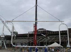
The rigid-base jumper’s (RBJ) pipe measures 18 in. OD and 1.125 in. WT. ASME B31.8 design code governed RBJ design. Maximum stresses follow the acceptance criteria defined in ASME for the hydrotest, installation, and operational load cases, considering fabrication and measurement tolerances. Pipeline end termination (PLET) expansion and contraction measure 0.6 and 0.5 m, respectively. Offtake spool displacements combined with PLET displacements define maximum stress load cases.
Cyclic loads from thermal expansion caused by shutdown and offtake spool motions must also be assessed to gauge RBJ fatigue damage. Fatigue analysis also considered damage from VIV, for both long-term and storm-current profiles. The RBJ’s approximate air weight is 45 tonnes. It is 38.7 m long, 13.9 m high, and does not require strakes (Fig. 2).
Monitoring system
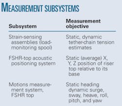
The accompanying table outlines the FSHR monitoring system.
The load-monitoring spool sits at the lower end of the tether chain and provides a real time indication of the tension supplied by the BC. The 18-in. OD spool measures axial strain at six equidistant locations around its circumference with pressure-balanced oil filled linear variable differential transformer-based extensometers.
The FSHR’s positioning package stands independent from the rest of the monitoring system, consisting of two ROV-retrievable acoustic beacons mounted on the TRA. An acoustic phased-array transceiver on the FPU’s acoustic Doppler current profiling carriage interrogates the beacons. The line of sight between the acoustic transceiver and the beacons on the TRA is unobstructed.
Petrobras’ Petronav software calculates final earth-fixed position relative to the FSHR base and related raw data. An Octans III standard motion package measures the 6 Degree of Freedom Motions (6DOF) and earth-fixed heading of the TRA. This package contains three high-quality linear accelerometers, three IXSEA fiberoptic rate sensors, and a compact microprocessor-based data acquisition system with embedded software to filter and integrate the sensor’s raw data.
FSHR installation
Technip’s Deep Blue performed the bulk of installation work on the FSHR system, with several other vessels in support. The riser remained partially flooded throughout installation. Full flooding occurred only after connecting the riser to the foundation. Flooding the entire riser took place before full dewatering of remaining BC compartments.
The heavy-lift vessel BBC Australia transported the BC from the Gulf of Mexico to Arraial do Cabo in the Campos basin. Preparation for the upending and tow of the BC occurred onboard, including installation of fairleads, umbilicals and tether chain, hydraulic connector, and a soft-landing device. The Australia’s two cranes lifted the BC and positioned it to float horizontally in the water.
Technip’s survey vessel Geoholm and the anchor-handling vessel (AHV) Geonisio Barroso assisted in upending the BC. Umbilicals and a manifold onboard the AHV controlled the upending operation. Flooding compartments 7 through 15 resulted in about 6 m of the BC remaining above water at the end of the upending process.
Towing the BC in this state took 66 hr to cross the 267 km to P-52’s location.
Deep Blue performed the following tasks while the BC was being readied:
- Keelhauling the LRA and suspending it on the HOM.
- Welding 32 riser quad joints.
- Transfer and welding of the UTSJ to the riser string.
- Temporary lowering and suspension of the riser string beneath the hull.
- Transfer and flange connection of the TRA to the riser string.
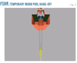
- Lowering and temporary hang-off of the riser assembly from moon pool pad eyes (Fig. 3).
Completing this work readied the riser for subsea connection of the BC.
The following occurred upon arrival of the BC at the installation site:
- Installation of guidelines to the TRA.
- Pendulum of the BC.
- Keelhaul of the BC from outriggers to moon pool.
- Connection of BC fairleads to the guidelines.
- Removal of riser suspension slings
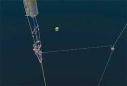
- Subsea connection of the BC to the TRA (Fig. 4).
- Deballasting the BC.
Offshore activities performed to connect the FSHR to its foundation included:
- Installation of the pull-down suction pile on seabed by the DB (the pile was later retrieved).
- Installation of the pull-down system on top of the suction pile by the DB.
- Installation of the pull-down buoys on the pull-down system by the DB.
- Transfer of buoyancy: preliminary deballasting to get the FSHR positively buoyant.
- Pull-down operations and locking the riser onto its base (Fig. 5).
- Final deballasting to in-place conditions.
- Cleaning all installation aids.
The deballasted FSHR floats at 50 tonnes positive buoyancy above the foundation before pull-down. The 45-tonne clump weight (CW) used by the DB to control the orientation of the BC also orientated the FSHR to the appropriate heading and controlled the buoys during pull-down. The DB deployed the CW to depth and connected it to the pull-down buoys. A 16-tonne CW connected to the bottom of the TRA allowed the Geoholm to maintain FSHR position in the current during pull-down.
Lay vessel Sunrise 2000 installed the flexible jumper. The vessel required modifications to install the 16-in. ID flexible jumper. An ROV-actuated hydraulic connector attached the gooseneck to the flexible jumper’s end at the FSHR side and vertically connected it to the mandrel at the TRA. Unreeling of the flexible jumper then allowed it to be pulled-in to the slot on the P-52. An installed closing spool connected the FJ to the P-52’s piping facility.
Installation HAZID
A hazard identification (HAZID) review preceded FSHR installation. Its results detailed the hazards identified, associated risks, and mitigating measures. The review also provided a summary of the action items arising from it. Each manager-engineer in charge of a particular process or task then took responsibility for ensuring all items under his supervision were closed out, completing action items prior to the commencement of installation operations whenever possible. Some actions, however, required on-site remediation.
Once work was under way, changes to scope, limits, etc. could affect the HAZID findings. The responsible engineer, therefore, would continually monitor any changes to the project and assess the need for any updates to the HAZID. An offshore management change procedure managed new work developed offshore or on site and performed risk assessment.


