VOC EMISSIONS—1: Study evaluates storage-tank VOC emissions reduction
A 6-month on site evaluation of volatile organic compound (VOC) emissions controls and control strategies determined advantages and disadvantages of various equipment and methods.
Recent regulations in Colorado as well as other oil and gas producing states have begun to require operating companies to control flashing emissions from storage tanks at oil and gas production sites.
The Trimeric Corp. and Noble Energy Inc. 6-month study in 2007 evaluated multiple types of three-phase separators, enclosed flares, and vapor-recovery units. The study looked at a new type of separator designed to reduce VOC emissions and separator fuel use. It found advantages and disadvantages for using slug catchers upstream of separators and surge bottles downstream of separators to reduce peak and average VOC volumes requiring treatment.
The study also evaluated the benefits of changing operational practices, including keeping a small amount of backpressure on storage tanks and reducing the volume of separator dumps.
The first of a two part series discusses regulations, typical operations, and study objectives. Part 2 will cover field evaluations.
The main conclusions of this study are that:
- Operation of production separators is linked closely to the optimal operation and design of associated VOC emission-control equipment. Separators can be designed and operated to minimize the size of associated VOC controls while increasing revenue by reducing gas flared or burned as fuel gas.
- Field testing of separators to prove out the economics of various designs of operating strategies presents numerous operational difficulties, especially for accounting and normalizing declining production rates.
- Proper sizing of flares based on peak flow rates is critical for good emissions control. Peak flow rates of flash gases depend on the flow characteristics of producing wells and the separator process configuration and operating conditions.
- Vapor-recovery units offer the potential for improved economics and reduced emissions but are more complex to operate than flares.
- Surge bottles and slug catchers, while introducing some additional complexity to production operations, are options for reducing peak flows and size of emission-control equipment. They also offer some potential for increased oil production due to improved oil-gas separation and reduced flashing losses.
Regulations
The Denver area has faced increasing air-quality requirements during the past several years in meeting the 8-hr ozone standard. In an early action compact (EAC) agreement with the US Environmental Protection Agency (EPA), the Colorado Department of Public Health (CDPHE) required control of flash emissions from oil and gas storage tanks beginning in 2005 as part of an overall strategy that also included requirements for glycol dehydrators, engines, and a reduction in gasoline Reid vapor pressure.
In developing a control strategy for condensate tanks, CDPHE worked with the industry to develop an innovative regulatory approach that required companies to achieve a certain percentage reduction in their emissions across the entire ozone maintenance area, rather than a traditional threshold-based approach to regulations, such as controlling all sources over a certain size.
As a result, the regulations created an incentive for companies to exceed the percentage reduction required so that isolated upset conditions, for instance from control equipment failures, would not cause a company’s overall percentage reduction to fall below the desired percentage target.
CDPHE’s Regulation 7 initially required a 37.5% reduction in emissions from storage tanks in 2005 and a 47.5% reduction in 2006 and beyond. Due to faster-than-expected growth in production and therefore flash emissions, CDPHE increased the level of control to 75% for 2007 and will increase it to 78% in 2011. Additional changes to this regulation are contemplated as part of the ozone state implementation plan (SIP) being developed during 2008.
Currently, Regulation 7 requires that control devices at each site reach at least a 95% reduction in emissions. Although performance tests have shown that the burners at many sites typically may have destruction efficiencies exceeding 99.5%, the industry’s concerns during the initial rulemaking in 2003-04 were about the potential for pressure relief valve venting at unmanned facilities as well as maintaining a tight seal around the hatch on the tank.
Because test measurements indicated that these possible leaks were relatively small in those limited instances where they did occur, the combined capture and destruction efficiency was set at 95% in the regulations.
Typical operations
This VOC study occurred at oil and gas production facilities in northern Colorado operated by Noble Energy Inc. To complete this study, Noble and Trimeric engineers worked closely with production personnel, emission-control equipment vendors, environmental staff, and others to carefully collect and analyze data on the operations of several types of separators, flare systems, vapor-recovery units, and associated strategies for reducing peak emission rates.
The work demonstrates that significant opportunities exist for improving and optimizing VOC emission controls, while in some cases even increasing revenue. The valuable lessons learned can serve as a useful resource for others with similar needs.
Noble’s operations in the Wattenberg field northeast of Denver are typical of exploration and production facilities in the area. The operations produce sweet natural gas and condensate. The condensate’s API gravity typically ranges from the mid-40s to the low 50s. This article refers to condensate as oil.
The wells typically have low average flow rates. The average production rate from all producers in Weld County in November 2006 was 36 Mscfd of gas and 2.6 bo/d. Production facilities only include separators, tanks, and emission controls. Wells at many of Noble’s sites flow intermittently with the aid of wellbore plunger lift. A control valve shuts in the plunger downhole between cycles, allowing reservoir fluids to enter the tubing above the plunger. At the beginning of the next cycle, the control valves toggle to let the plunger move freely.
Reservoir pressure causes the plunger to rise rapidly. When the plunger is moving, it forms a seal with the inside surface of the tubing wall. Thus, all fluid above the plunger arrives at the surface production equipment in a very short time (5-30 min). Because the fluid arrives in slugs to the separation equipment, the design and operation of any emission-control system must consider not only the average flow but also the peak flow.
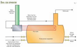
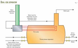
Separators at the sites typically are either dual coil or HLP (Figs. 1 and 2). The dual-coil separator is the simpler of the two designs, consisting of a single-stage, heated three-phase separator. Production from the wells first goes through a coil inside the separator that a fired heater heats during certain times of the year. Production fluid retained in the separator submerges the coil, and the high-pressure well stream fluid inside the coil receives heat before decreasing the pressure through a valve that feeds the stream into the three-phase separator.
The dual-coil separator has two separate inlet coils and pressure letdown valves to allow simultaneous processing of production from two wells that might operate at different pressures. Gravity separates the oil and produced water before the fluid level control valves discharge the fluid to separate storage tanks.
Gas from the separator enters the sales pipeline, with a portion used as fuel for the fire-tube heater inside the separator. The separator is heated seasonally, nominally October through April, to facilitate the oil-water separation step.
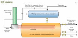
The HLP separator has two separation stages. The first stage is a two-phase separator for separating sales gas from the oil-water mixture. The first separation stage in the HLP typically operates at lower temperatures than the dual coil.
The oil-water mixture is then reduced in pressure and fed to the low pressure, three-phase separator. Flash gas produced in the low-pressure separator goes to the storage tank for disposal and then usually to an emission-control device. Oil and water from the low-pressure separator again are heated seasonally in the low-pressure separator with a fire tube to facilitate the oil-water separation step.
In both separators, the VOC emissions originate primarily from the flashing step, as the pressure is reduced between the separator pressure and atmospheric-pressure storage tank. Flashing losses are emissions that result as liquids flash to pressures below their bubblepoint pressure. The amount of flash emissions at a given location depends on many factors, including the type of unit operations (such as the number of stages of separation), the temperatures and pressures of the unit operations, and variations in flow rate and operating conditions.
The Colorado Oil and Gas Association (COGA), in conjunction with CDPHE, developed an average emission factor of 13.7 lb of VOC/bbl oil. This value is used commonly; however, site-specific emission factors may range from about 50% up to 200%+ of this average factor.
In addition to the flashing losses, working losses can occur as vapors that are displaced from the storage tank headspace as the tank fills. Breathing losses, also known as standing losses, can occur as temperature and pressure in the storage tank fluctuate and volatilize lighter components. Often, these fluctuations in the storage tank result from daily temperature swings.
Study objectives
This study primarily focused on identifying reliable, field-proven, cost-effective methods for complying with the Regulation 7 VOC emission-control requirements for storage tanks. Project objectives were met by measuring, understanding, and evaluating flashing losses for different separator and emission-control configurations in operation at these facilities.
The options evaluated may be classified as follows:
- Separator modifications.
- Peak-flow management approaches.
- Improved flare technologies.
- Vapor-recovery units.
Separator modifications may include mechanical design changes as well as process optimization to reduce emissions. For process optimization, the temperatures and pressures in the high and low-pressure (HP and LP) vessels of the HLP separator may be varied within operational constraints to reduce emissions and increase revenue.
The feed to the separation equipment may limit the range of operating combinations in each separator; for example, feeds with high paraffin content require higher seasonal firing temperatures in the LP separator to break the paraffins. These high temperatures can reduce oil production and increase flashing losses when compared to a feed with lower paraffin content, which allows a lower temperature in the LP separator.
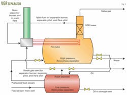
Mechanical design changes to the separator involved additional equipment, such as the VGR separator that was tested. Fig 3 shows a VGR separator that has two separation stages. The VGR has a packed tower on top of the high-pressure separator. This tower is one of the main design differences of the VGR compared with the HLP and dual-coil separators.
The packed tower sharpens the hydrocarbon separation in the produced oil and gas by sending more light hydrocarbons out with the sales gas and keeping more heavy hydrocarbons in the sales oil. In general, the heavier hydrocarbons are worth more when sold as oil than as natural gas. Similarly, the operator recovers more value from the methane and light ends when these components go into the sales gas and the flashing losses due to these components are reduced at the storage tank.
Another key difference in the VGR compared with the HLP and the dual-coil separators is that some gas from the low-pressure separator (called the flash absorber in the VGR) serves as fuel for the separator pilot, separator burner, and flare pilot. By contrast, the HLP low-pressure separator gas goes to the storage tank and then to the control device.
The dual-coil separator does not have a low-pressure separator.
The intent of peak-flow management approaches is to mitigate negative effects of flow variations on flashing losses. For example, slug catchers may be installed between the well and separation equipment. Additionally, surge bottles with appropriate controls may be installed between the separation equipment and the atmospheric storage tanks.
The slug catchers and surge bottles provide a buffer for the separation or control equipment and reduce capital requirements because the separation and control equipment can have a size for less than the peak-flow rate. Part 2 of this series will discuss appropriate strategies for the design and controls of surge bottles and slug catchers.
Once the facility generates emissions, two control approaches generally are used: combustion and vapor-recovery units (VRUs). Combustion may include open or enclosed flares, also referred to in the field as burners.
Enclosed flares have several advantages over open flares. These flares typically have a higher destruction efficiency than open flares, a flame not visible from outside the vessel, and easier combustion control.
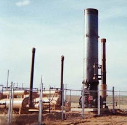
Fig. 4 illustrates a typical enclosed flare. This enclosed flare has a 48-in. diameter and is the largest stack in the photo. Some key features of this flare are:
Combustion emission-control options typically have lower capital and operating costs than VRUs, are more reliable, require less maintenance, and do not risk oxygen contamination of sales gas.
Drawbacks to using flares in this application are loss of additional sales-gas revenue, which can be obtained with a VRU, and generation of combustion byproducts, including NOx, CO, and CO2.
One must also evaluate safe work practices and concerns regarding high-temperature equipment when using enclosed flares in this application. While maintenance is lower with flares compared to other control strategies, the flares require regular service, including clearing condensate from the inlet-gas line, verifying pilot operation, ensuring that bird screens are clean and in place, and verifying that the flame arrestor on the feed-gas line and on the air inlet ports are clear.
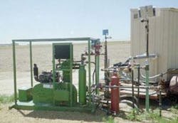
VRUs come in many configurations that utilize single-stage or multistage compressors, eductors, and other configurations for operation with associated separation equipment. Figs. 5 and 6 show two types of VRUs evaluated in this study. Part 2 of this series will describe in more detail these VRU systems.
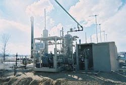
VRUs can generate revenue by capturing and compressing gas that otherwise would be vented or burned and then adding this high-btu gas into the sales-gas stream. Compared with flares, however, VRUs typically have higher capital and operating costs, are more complex, require more maintenance, can be less reliable, and may cause oxygen contamination of sales gas streams if storage tanks are not controlled and blanketed properly.
Based on a presentation to the Gas Processing Association Annual Convention, Mar. 2-6, 2008, Grapevine, Tex.
The authors

Ray McKaskle ([email protected]) is a senior engineer at Trimeric Corp., Buda, Tex. He has 16 years of experience in process engineering and currently works with oil and gas clients and on government research projects on emission controls, plant debottlenecking, carbon dioxide sequestration, and system and facility design. Prior to joining Trimeric, McKaskle held process engineering positions with Novellus Systems Inc. and Radian Corp. McKaskle has a BS in chemical engineering from Oklahoma State University and is a registered Professional Engineer in California.

Kevin Fisher ([email protected]) is a principal engineer at Trimeric Corp., Buda, Tex. He has 20 years of experience in process engineering, research and development, and troubleshooting for oil and gas production and oil refining clients, as well as for private and government-sponsored research programs. Fisher specializes in acid gas removal, CO2 capture, gas processing, and gas dehydration. He has an MS in chemical engineering from the University of Texas at Austin, and BS chemical engineering and chemistry from Texas A&M, and Sam Houston State University, respectively.

Katherine Searcy ([email protected]) is a senior engineer at Trimeric Corp., Buda, Tex. She has consulted to the chemical, oil and gas, utility, and biorefining industries for about 10 years. Searcy provides clients with process engineering, research and development, and early-phase process evaluation services. She has a BS in chemical engineering from Texas A&M University and is a registered Professional Engineer in Texas.

Curtis Rueter is the environmental and regulatory manager, Northern Region, for Noble Energy Inc. He is responsible for overseeing permitting of wells for drilling and compliance activities during operations, such as storm water management, spill prevention control and countermeasures, and air permitting. Prior to joining Noble, he was with the Wind River Environmental Group, CrystaTech, and Radian Corp. Rueter has a BS in chemical engineering from Texas A&M University.