Balloon network allows remote CP monitoring
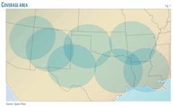
Automated near-space monitoring of pipeline rectifiers offers a means of maintaining cathodic protection of pipeline networks without travelling to remote locations. Space Data Corp. uses standard weather balloons and a patented GPS navigation system to maintain a continuous monitoring presence above the Southwest US and northwestern Gulf of Mexico (Fig. 1).
In addition to remotely monitoring cathodic protection, SkySite enables general supervisory control and data acquisition host polling; pump-off controller monitoring; alarm monitoring of storage tanks, compressor stations, and transmission lines; field communications; and flow monitoring.
System overview
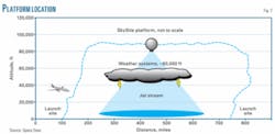
Located about 20 miles above the earth, Space Data’s SkySite platforms operate above flight paths, the jet stream, and weather systems, but below satellites (Fig. 2). The system already monitors wells and storage facilities in the region; it operated without interruption across its entire coverage area, including much of Louisiana, during Hurricane Katrina.1
Launches of new balloons carrying SkySite platforms occur every 8-12 hrs. Each platform covers more than 400 sq miles of earth and stays aloft for about 24 hrs,2 enabling wireless data communication in areas not served or poorly served by existing wireless technologies. Launch typically takes 20 min. and occurs without US Federal Aviation Administration restriction because the platforms are light enough to not pose a threat to aircraft safety, according to Space Data.
Communication occurs on Space Data’s own narrowband frequency spectrum (1.7 Mhz of the 901-940 Mhz band), minimizing interference, and uses fixed IP addresses required by SCADA systems.
Space Data’s SkySite network consists of three primary components. The SkySite platform itself uses a standard Motorola ReFLEX 2.7, 2-way packet data communications protocol and includes communications, control electronics, power, and other components needed to provide wireless data services. Use of this protocol also allows use of other 2.7-compliant devices such as two-way pagers.
Ground facilities, spaced at roughly 400-mile intervals, include remote tracking stations, launch sites, and associated telecommunications links between the balloon transmitters and network operations center. Among these links is an API 21.1-compliant wireless modem located between the monitored asset and SkySite platform and used with remote telemetry units and electronic flow meters communicating via a serial interface.
The Arizona-based network operations center connects Space Data monitoring equipment with its subscribers. Space Data contracts with property owners in favorable locations to conduct launches.
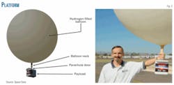
Fig. 3 shows the SkySite platform. A 1.5-kg biodegradable latex balloon (about 25 ft in diameter, inflated) uses hydrogen to lift the monitoring payload. An o-ring holds the balloon neck to a tube on top of the payload. The Styrofoam-enclosed payload weighs less than 6 lbs and has a target weight of 3.5 lbs. When the balloon has exhausted its ballast, reached the outside edge of its service area, or the payload’s power source has depleted, the payload releases and returns to earth by parachute.
Space Data tracks the payload during both operation and descent through GPS, recovering the majority of the payloads, which it then refurbishes and reuses. It includes contact information on each of the payloads to help ensure this occurs and is developing a steerable parachute for the system in hopes of making payload recovery even easier.3
Cathodic protection
The SkySite system remotely monitors a wide variety of rectifier applications, including pipe-to-soil measurements and critical bond reading. The system also automates weekly-monthly rectifier runtime reports, including notification of minimum-maximum anomalies and power outages.
The system’s fully 2-way communication link allows control as well as monitoring. The control center can remotely change monitoring parameters or exception alarm programming on either a device-by-device basis or across the entire system.
Field testing
Space Data placed monitors on a crude pipeline in West Texas at four locations, using off-the-shelf electronics and enclosures as part of a 60-day trial beginning June 15, 2006.
The system monitored pipeline rectifiers to the operator’s satisfaction, but need for improvement was noted regarding the ground unit’s scale, cost, and user interface (which was deemed overly complex).
A second multi-client round of trials began in August 2007, with equipment installed at a variety of locations including a standard AC rectifier, a DC-powered rectifier, and a gas-fuelled generator. Devices responded at a 98% rate during the trials and customers reported satisfaction that initial shortcomings had been addressed.2
References
- Statement of Jerry Knoblach, Chairman and CEO, Space Data Corp., before the Federal Communication Commission’s Independent Panel Reviewing the Impact of Hurricane Katrina on Communications Networks, Washington, D.C., Mar. 7, 2006.
- Decker, L.N., Knoblach, J., and Kitchin, J.C., “Trials and Tribulations in Wireless Automated Pipeline Rectifier Monitoring,” NACE Corrosion 2008, New Orleans, La., Mar. 16-20, 2008.
- Drucker, E. “Wireless Balloons,” WirelessWeek, Apr. 1, 2008.


