Field work cuts threat to suspended pipeline
Field experiments have reduced the likelihood of damage or failure of a suspended gas pipeline span as a result of pigging. The potential displacement and vibration caused by pigging pose particular problems in suspended spans. Great enough displacement or vibration could create deformation of the line or failure.
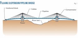
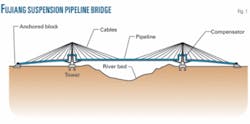
The Fujiang pipeline bridge on the north main line of the Sichuan natural gas transmission network lies about 200 m upstream of the main Fujiang river bridge. Fig. 1 shows the structure of the Fujiang pipeline bridge. The bridge uses two 50-m towers, with the pipeline suspended by diagonal cables. The main pipe span measures 320 m. The two spans running between each tower and the riverbank measure 150 m.
The pipeline consists of 720-mm OD, 12-mm WT steel pipe. Diameters of the cables range between 22.5 and 45 mm. The towers used welding construction. The cables alone support the pipeline. The pipeline bends 10 m upward at each tower as temperature compensation. The overall structure is highly flexible.
The liquids encountered during pipeline pigging create particularly heavy loads at the bends, heightening the possibility of leaks and damage.
This article details both the static and dynamic tests conducted at Fujiang crossing in an effort to find a scientific basis for drafting vibration absorbing measures.
Static tests demonstrated little difference between horizontal and vertical damping ratios and the higher the frequency, the smaller the damping ratio. Dynamic tests showed that the maximum vibration displacement of the Fujiang pipeline crossing did not occur at the middle of the main span, but instead somewhere between the 1⁄4-mark and the middle.
Dynamic characteristics
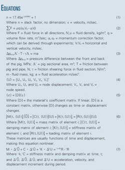
Pigs drive the fluid in front of them, formng slack two-phase flow. Flow patterns and liquid content change dynamically, creating continuous loading change when pigging is under way. Introducing a slack factor determines dynamic loading of the crossing during pigging. Similarity principle and laboratory experiments determined the slack factor (Equation 1).
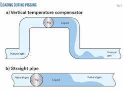
The change in flow direction at the vertical temperature compensator (Fig. 2a) creates an impact load at the elbow. Momentum theory guides development of a mechanical balance equation (Equation 2), allowing calculation of the impact load.
Friction of the pig and pressure differences between the flow preceding it and the flow following it create changes of velocity in straight-line segments (Fig. 2b). The Hamilton principle guides deduction of the straight-line axial flow, which in turn informs construction of a mechanical balance equation (Equation 3).
As a pig drives the slack fluid through the crossing, it will create an active force and deform the pipe. The deformation will change fluid flow parameters such as liquid-containing rate, speed, and pressure. The change of flow parameters will in turn affect the crossing’s vibration properties, displacing the crossing and creating large vibrations. These factors prompted application of a large displacement, minor-strain nonlinearity finite element method to analyze the dynamic characteristics of crossing during pigging.
Ascertaining dynamic characteristics of the crossing during pigging requires prior establishment of basic differential equations regarding the pipeline, cables, and towers. Geometry required assessment of nonlinear factors such as initial internal force at the crossing, rope sag, and equivalent variable cross-section beam dynamics. Analysis assumed that ropes were tensional, not based on compression. The special finite element method guided the setup of basic differential equations.
Boundary constraints of the main components of the crossing structure followed establishment of the fundamental equations of the pipeline, ropes, and towers. These included:
- Anchored block. The displacement and angle deformation of the pipeline at each anchoring block direction equals 0.
- Junction between tower, cables. The Fujiang pipeline crossing featured cable element nodes and tower element nodes with identical displacement and angle deformation, caused by an inability to separate slides between the dragline and the tower top.
- Junction between cables, pipeline. Welding the cable to the pipeline’s junction blocks gave the cable element node and pipeline element node identical displacement and angle deformation.
The crossing’s structural properties, geometric nonlinearity, and dynamic loading characteristics allow building a nonlinear finite element model. Equation 4 expresses basic node displacement. Equation 5 shows the finite element’s relationship between stress and strain.
The d-Alembert principle allows building the elements’ fundamental kinetics equation (Equation 6).
Analyzing the dynamic characteristics of a pipeline bridge suspended by diagonal cable required initial definition of the crossing’s incremental kinetics using the Lagrange UL column (Equation 7).
These matrices are typically implicit functions of time and displacement, solvable through adopted subspace iteration, Newton-β, and modified Newton-Raphson methods.
Field testing
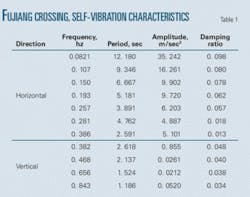
Static and dynamic tests measured the Sichuan Jiangyou pipeline bridge’s properties. The static test first measured the crossing’s self-vibration frequency, amplitude, damping ratio, and the cables’ inner force using the environment random stimulation method. Table 1 shows select results of static testing.
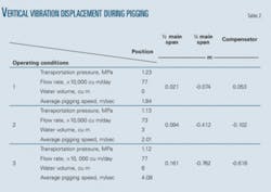
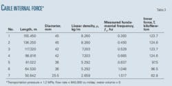
Dynamic tests then measured acceleration and vibration parameters at each position. Devices set up at each end of the crossing for compression, water injection, and pig launch and receiving controlled water quantity and pig speed during testing. Testing measured displacement, pipeline inner strain, and cable inner strain in varied operating conditions at each 1⁄8 increment of the crossing is main span, at the gantry, and at the temperature compensators. Tables 2 and 3 show select dynamic testing results.
Results, analysis
Combined theoretical analysis and field testing simplified the complicated flow in the vertical temperature compensator, yielding slack factor n, which provided a basis to evaluate dynamic loading near the compensator. Using the bridge’s initial position as a reference point provided the basis for establishing finite element balance and kinematics equations according to the Lagrange UL column matrix.
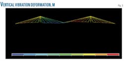
The models described in this article, combined with finite element analysis software (ANSYS), simulated and predicted vertical vibration of the Fujiang pipeline crossing during pigging. Maximum displacement of 0.417 m occurred somewhere between the 1⁄4-mark of the main span and the span’s middle (Fig. 3).
Table 4 compares measured values from testing with calculated values; finding agreement and validating the vibration absorption theories.
null
Acknowledgment
This article was financially supported by Science and Technology Fund No. 2007xjz016 of Southwest Petroleum University.
Bibliography
Laugesen, S., “Active control of multi-modal propagation of tonal noise in ducts,” Sound & Vibration, Vol. 195, No. 1, pp. 33-56, 1996.
Li Chang-jun, Wang Yu-chun, and Wang Yuan-chun, “Analysis of the Vibration in Gas Pipeline System,” Natural Gas Industry, Vol. 20, No. 2, pp. 80-83, 2000.
Paidoussis, M.P., and Li, G.X., “Pipes conveying fluid: a model dynamic problem,” Journal of Fluids and Structures, Vol. 7, No. 2, pp. 137-204, 1993.
Wiggert, D.C., Lesmez, M.L., and Hatfield, F.J., “Modal analysis of vibrations on liquid-filled piping systems,” ASME-FED, Fluid-Structure Interaction No. 56(b), pp. 107-113, 1987.
Zhang Li-xiang, Huang Wen-hu, and Tijsseling, A.S., “Review of FSI analysis of fluid-conveying pipes,” Journal of Hydrodynamics, Vol. 15, No. 3, pp. 366-378, 2000.
Zhang Zhi-yong, Shen Rong-ying, and Wang Qiang, “The Modal Analysis of the Liquid-Filled Pipe System,” Acta Mechanica Solida Sinica, Vol. 22, No. 2, pp. 143-149, 2001.
The authors
Li Chang-jun ([email protected]) is superintendent of the oil and gas storage and transportation department of Southwest Petroleum University and is also a professor at SWPU, Chengdu. He holds an MS degree in oil and gas storage and transportation from SWPU (1988) and is a member of the China Petroleum Association.
Zhu Xiao-lan ([email protected]) is studying for her MS in oil and gas storage and transportation at SWPU, Chengdu. She holds a BS in the same field of study from SWPU (2005).
Liao Ke-xi ([email protected]) is an assistant professor of petroleum engineering at SWPU, Chengdu. He holds a PhD in oil and gas storage and transporatation from SWPU (2001) and is a member of the China Petroleum Association.
Liu En-bin ([email protected]) is a lecturer in petroleum engineering at SWPU, Chengdu. He holds an MS degree in oil and gas storage and transportation from SWPU (2005).
