Tools aid discovery of fatigue cracks
A suite of examination techniques is used to discover fatigue cracks in drilling components. Fatigue is the most common cause of drillstem failure and can occur at stresses well below the normal operating stress in most drillstem components.
Several factors influence fatigue, a complex mechanism, including material properties, mud corrosiveness, drilling trajectory, rotary speed, loads, and several others. This complexity plus the lack of meaningful knowledge about the amount of prior fatigue damage, makes accurate, absolute fatigue life prediction practically impossible.1-3
In practice, there is no reliable method to quantify the total amount of fatigue damage a component may have accumulated. Rather, present inspection technology is limited to looking for fatigue cracks. Even when these inspections are performed properly, they can still occasionally fail to find small cracks.3
Most of the fatigue life of a drillstring component is used up by the time a crack has formed and grown large enough to be detected by inspection; therefore, a fatigue crack, once detected, is cause for immediate rejection of the component.
How quickly a fatigue crack will form and propagate to failure depends on many variables, here called drivers.3 The four major drivers are:
- Mean tensile stress. Higher mean stress shortens fatigue life.
- Cyclic stress excursions about the mean stress. Larger stress excursions shorten fatigue life.
- Corrosiveness of the mud system. More corrosive environments shorten fatigue life.
- Fracture toughness of the material. Tougher materials (high KIC) will have a longer fatigue life and support a larger crack before final failure. Fracture toughness, rather than being a driver of fatigue damage, should be thought of as a retarder.
Case study 1: drilling jar
We examined the fatigue failure of a drilling jar. One section of a drilling string, the drilling jar, failed during drilling operations at 9,943-ft depth. A high torque value of 13,000 ft-lb, sudden loss of string weight (40,000 lb), and a drop in mud pressure (900 psi) were noted in geoservice logs at the time of failure.
Immediately after the jar rupture, the drillers requested fishing tools to retrieve the parted piece. They replaced the failed section and recommenced drilling.
After the fishing operation, the operator reviewed all documents related to the drillstring and particularly the parted jar. They also reviewed pre-job inspection reports and found they were adequate according to the manufacturer’s procedure, as documented in the company quality management system.
The company’s inspection included full magnetic particle inspection (MPI) and visual thread inspection of the failed jar components and connections before they were put in service. Independent, third-party inspectors also inspected and certified the failed jar.
Based on this, the company decided to conduct independent investigations with samples from the failed jar, accompanied by the internal failure investigation report and geoservice logs.
Investigation, results
The investigation included visual examination, macroscopic examination, X-ray analysis of the attached deposit on the failed piece, and mechanical assessment (hardness test) of the received jar sample.
Visual examination. The jar bottom sub was carefully cleaned using a special solution and then subjected to a visual check, which revealed:
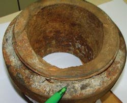
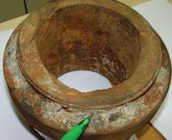
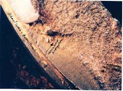
- Failed jar sub showed pronounced brittle failure (i.e. fatigue cracks and overload) and little ductile tearing (Fig. 1).
- Small corrosion pits that developed under deposits are visible. The corrosion most likely occurred because oxygen was present (Fig. 1). Halides, such as chloride ions, can also accelerate localized corrosion.
- Sign of ratchet marks were visible on the parted jar. Fatigue cracks originating at the external (threads) and internal (corrosion pits) jar surface were visible.
- Extent of fatigue cracks or areas covered by the fatigue marks were small, isolated, and extensively distorted. The number of fatigue cracks, however, originating from the jar connector (external threads) was greater compared with those initiated from the internal surface (corrosion pits).
- Jar connectors or threads have acted as a potential site for initiation of fatigue cracks from the external surface while corrosion pits (oxygen corrosion) have acted as a stress raiser or potential initiation of fatigue cracks from the internal surface.
- About 50% of the fracture surface was flat, brittle fracture without any sign of marking or plastic deformation (Fig. 1). This type of fracture surface resulted from the overload or high torque exerted on the drilling string including the failed jar.
- All fatigue markings (ratchet markings) were visible on one side of the jar fracture surface. This may be because of drilling with high torque in a dogleg zone or a highly inclined borehole. This can be confirmed from the drilling data sheets or daily report.
Macroscopic examination. This confirmed all the findings of the visual examination. The failed jar showed a large, flat area with several isolated fatigue markings.
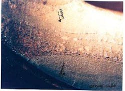
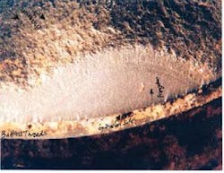
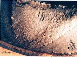
Figs. 2-5 show that a few initiated at the external thread connector and others initiated from small corrosion pits (internal surface). Mechanical curvature, dents, and corrosion pits can act as stress raisers where fatigue cracks may initiate. The initiation stage usually takes more time compared with the propagation stage. Propagation depends on operating conditions and mechanical properties of the materials.
The macroscopic examination confirmed that the fatigue cracks seem to have propagated during a short period of time due to cyclic loading and unusual drilling operations or conditions (inclination, bending, high stresses/torque, etc.). In addition, the fracture surface showed deformed (nonuniform) fatigue marks, rough fatigue markings, and opposite-propagated fatigue cracks (Figs. 2-5). This indicates that the string operated under high torque and stress levels and the fatigue propagation rate was quite fast.
Macroscopic examination also confirmed that about 50% of the jar fracture surface was flat and the rest was slightly inclined, resulting from overload failure. Small corrosion pits initiated at the jar internal surface were also evident.
Hardness. The Vickers hardness-testing machine (10 kg) was used to measure across the jar’s cross-section. Hardness was up as specified.
X-Ray diffraction. The compound found on the jar connector (buttress threads) was collected and subjected to X-ray diffraction. It was composed mainly of calcium carbonate (94% calcite), silica, and a little potassium chloride.
Failure mechanism, jar
In the light of results of the fracture surface examination, chemical analysis, and hardness measurements, in addition to the reviewed geoservice log documents, we suggest the following jar failure mechanism:
1. The jar integrity was weakened by the development of several fatigue cracks at the jar threads connector as well as from localized corrosion pits. The exerted load also assisted the initiation. These cracks seem to propagate quite fast due to severe working conditions and operations, i.e., high string deflection, drilling in dogleg areas, high torque, high rotation, etc.
The inspection did not reveal the propagated minute cracks. It was difficult to confirm whether these cracks initiated before or after the last conducted inspection. This requires us to establish the crack propagation rate and some calculations.
2. Several propagated fatigue cracks reduced the jar total cross-sectional area; therefore, the failure is expected when high load or torque (remaining sound material can no longer carry the applied load) was exerted during the drilling operation. The jar failure mechanism depends on the toughness of the jar materials (KIC). It seems that torque exerted during drilling (14,000 lb) was high enough, and in presence of small isolated fatigue cracks, to lead these minute cracks to propagate quickly, resulting in overload and catastrophic rupture of the jar.
The nondestructive test techniques and procedures used, such as MPI, do not seem to detect small fatigue cracks in the jar threads. As previously mentioned, the observed fatigue marks (ratchet marks) extended over small and isolated areas on the jar fracture surface. In addition, some of the examined fatigue cracks showed a tiny initiation point or site, indicating that only small part of the crack will be apparent (external surface) and the rest will propagate through the jar’s cross section.
Based on these findings, we suggested that the company change the inspection procedure and technique to avoid any misinterpretation during the inspection process.
Jar determination
We can summarize the lessons learned from the failed drilling jar:
- The drilling jar failed catastrophically due to high torque during drilling operations. The fatigue cracks initiated at the jar threads and those initiated from corrosion pits reduced the load-bearing capability (reduced the cross-sectional area) and therefore assisted in the jar’s premature failure.
- Observed fatigue cracks seem to propagate over a short time. Rough fatigue marks were visible on the examined fracture surface, which indicates that high load or torque was applied to the drilling string.
- Jar connectors (threads) on the external surface and corrosion pits on the internal surface acted as “stress raisers” where the fatigue cracks initiated.
- Using MPI on the threaded components is sometimes insufficient to detect the fine fatigue cracks. The inspector should consult nondestructive testing experts regarding conducting additional testing techniques for thread inspections.
- The proper torque needs to be applied when the joint is made up (make up torque).
- Drillers need to be aware of the limits for applied torque, weight on bit, and rotation (rpm) while drilling in the dogleg zone and at high inclination to avoid buckling. Drilling outside of recommended limits endangers the integrity of the drilling tools and reduces markedly the working life.
Case study 2: drilling stabilizer
We received a sample from a failed 123⁄16-in. ID drilling string stabilizer. We were asked to conduct a detailed metallurgical investigation and to establish the main cause of string stabilizer failure. The failure report included stabilizer dimensions, material, stabilizer number, last inspection date, and the geoservices logging chart.
We conducted visual and microscopic examinations on the fracture surface of the failed part (extracted piece) after the pieces were cleaned with special chemicals and brushes.
Examination confirmed that the string stabilizer failed predominantly in a brittle manner. The fracture is partly planar and covers about 70% of the total fracture surface. The rest of the fracture was inclined 45º, which is a ductile rupture.
Shear leaps, twisting, and washout were all visible on the collar sample. Small washouts occurred due to high drilling-fluid pressure leakage (pressure drop was reported in geoservice chart) followed by the complete failure (separation) of the stabilizer.
The flat fracture of the stabilizer was due to initiation of multiple fatigue cracks at the thread roots of the last four threads. These cracks extended or propagated throughout the stabilizer wall thickness during service wall thickness during services such as drilling at a high rotation rate, drilling through a dog-leg; high loading on the bit, buckling and vibration when drilling hard rock zones, etc.
The rate of crack growth or propagation depends on the material fracture toughness and applied load. The applied load, due to stressed threads, should be below the fatigue endurance limit for the stabilizer material.
Visual examination. We scrutinized the fracture surface and threads of the failed string stabilizer. The fracture surface was partly flat, typical of brittle failure, and partly inclined by 45º, typical of shear or ductile failure.
Washout was visible on the failed stabilizer. This may have occurred due to leaking high-pressure drilling fluid before failure. The geoservice chart, which reported a pressure drop of 150 psi before the final failure, confirmed this.
Over the flat area of the fracture surface, noncontinuous beach marks typical of fatigue failure originated from the thread root. These beach marks appear to have originated from multiple initiation sites at the thread root (8½-in. OD female box), where high residual stresses are attained. The beach marks were found across 70% of the total fracture surface of the failed stabilizer. The remaining 30% were inclined, however, typical of ductile failure.
In some areas, beach marks appeared rough, indicating that the stabilizer was subjected to high stresses (bending stresses and vibration) or to high load rate. Recent geoservice data just before failure show high applied torque (up to13,800 ft-lb), which exceeds the allowable or recommended value.
Shear lip, indicating the final fracture due to overload failure, was visible on various areas on the fracture surface, such as the external side (outer rim) of the stabilizer as well as the inclined surface. Shear lips over a thin area along the rim of the stabilizer confirms the difficulties in detecting the fatigue crack from the external surface even when a wet fluorescent magnetic particle was used.
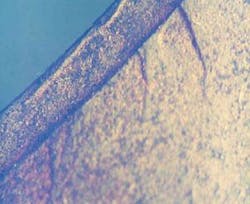
Microscopic examination. We examined the failed part of the stabilizer in a low-magnification stereomicroscope. This confirmed that the stabilizer failed due to the initiation of multiple fatigue cracks at the thread root (Fig. 6).
Generally, thread roots attain maximum residual stresses, which are introduced during machining. The level of stresses depends on the thread morphology. The magnitude of residual stresses is high when the applied load or torque is above the allowable range.
The applied load (dead load, load on drilling pit) and torque during drilling seem to be high in some cases. This was clear from the morphology of beach marks (fatigue crack steps, Figs. 7 and 8).
Shear leaps were evident on the outside of the external surface. The shape of the final fracture (shear lip) indicates that the stabilizer before failure was subjected to twisting (Fig. 8). This is imminent before complete failure where fatigue cracks have already propagated over a large area and only a small section is carrying the load.
Hardness. Measured hardness of the small specimens cut out of the received string stabilizer met the required specification.
Failure mechanism
Failure of the string stabilizer is mainly due to the fatigue failure that initiated from the most weak and stressed area of the stabilizer (threads of 81⁄8-in. OD female box). The fatigue crack initiated during drilling operations, i.e., drilling in the dogleg area, string buckling, string bending, etc.
High load on pit, high torque, or service load (abnormal load) all initiate fatigue microcracks at the thread roots (a0). Initiated cracks grow during drilling operations until they reach a critical size (ac), at which catastrophic failure of the string stabilizer is imminent. Fatigue cracks in this case were mainly flat; others were inclined 45º as a result of overload.
Generally, development of a fatigue crack can be divided into two main steps:
- Incubation and initiation of microscopic cracks. Detection of the flaw is impossible due the minute size of the crack.
- Propagation of the microscopic crack until it reaches a critical size. In this case, detecting the crack is possible; however, the propagation duration is shorter than the initiation stage, particularly when the drillstring was abnormally used.
The company technical report stated that the last conducted inspection on the failed stabilizer was 1 month before failure occured. In addition, the company technician conducted an additional inspection on the failed stabilizer; no cracks were detected in the failed stabilizer.
A professional inspection of the drilling string is necessary, particularly on the threaded areas. Visual inspection of threads on the box side is difficult and alternative methods such as ultrasound, which is more reliable than MPI, should be considered. A shear wave ultrasonic system can detect transverse fatigue cracks. An array of several transducers with sound beams overlapping can detect flaws.
Other versions of ultrasonic measurements can detect cracks in the threaded box connection. A 4º wedge allows compression-wave ultrasound with a frequency of about 10 milli-hz to enter the ends of a shouldered connection at a suitable angle for directing a beam along the thread roots.
Stabilizer determination
After examining the failed stabilizer, we conclude:
- The string stabilizer failed due to the initiation of multiple fatigue cracks at the thread root. Cracks propagated during stabilizer operations (string-up/string-down), vibration, inclined drilling string (buckling/bending), etc., until they reached a critical size before final fracture.
- High applied torque, load on bit, rotation, and the hole shape (dog leg) may have accelerated the stabilizer failure.
- The last inspection, conducted 1 month before failure, did not detect the propagated fatigue crack. One can estimate the propagation stage of fatigue cracks using a scanning electron microscope and calculating the number of cycles from the present fatigue striations on the stabilizer fracture surface.
- Fatigue cracks extended across 70% of the fracture surface. The remaining 30% failed by overload (shearing).
- A sign of little washout due to drilling fluid leakage and twisting before final failure were visible on the string stabilizer sample.
- The 150-psi pressure drop, as was reported in the geochart, is due to the first leakage (washout) or erosion through the stabilizer wall thickness. Complete separation or final fracture of the stabilizer then occurred.
- Morphology of beach marks in some areas confirms that the applied load was high.
- Some threads suffered from some galling, cuts, and dents, which were on the last threads.
- The lack of a professional inspector or inspection techniques to detect the fatigue cracks led to the catastrophic failure of the string stabilizer (cost of drilling rig standby time).
General recommendations
Fatigue control and drillstring inspection are critical to maintaining drilling equipment.
As previously discussed, fully predicting and totally eliminating fatigue in drillstrings is probably not possible. Fatigue, however, can be controlled and it requires an understanding of:
- The drivers that are steadily damaging the drillstring in small and irreversible steps.
- Work to reduce or weaken the drivers using all practical means. By doing this, companies can reduce the rate of fatigue damage accumulated and the crack propagation rate. This lengthens time between failures.
- The greater chance of finding cracked components via inspection rather than via downhole failure. Finally, the inspection must be performed properly to give the highest probability of finding cracks when they exist.
- Controlling fatigue in the well planning and drilling phases entails three simple objectives:
- Reduce the magnitudes of mean stress (torque) and stress excursions.
- Monitor and reduce the corrosion rate in the mud system.
- Inspect the components properly and at optimum intervals.
Inspecting the drilling string includes:
- Reviewing the inspection procedure adopted by Weatherford and third-party inspection teams. A professional nondestructive testing consultant should perform this inspection.
- Using other inspection methods such as eddy currents. Fatigue cracks can be fine and sometimes not easily detected using MPI. In addition, fatigue cracks sometimes initiate in the subsurface.
References
- ASM Handbook, Failure Analysis and Prevention, Vol. 1, 8th ed., Materials Park, Ohio: ASM International, 1986.
- Fatigue and Fracture, Vol. 19, ASM Handbooks, ASM International, 1996.
- Vaisberg, O., Vincke, O., Perrin, G., Sarda, J.P., and Fay, J.B., “Fatigue of drillstring: state of the art,” Oil and gas science and technology, Rev. IFP, Vol. 57 (2002), No. 1, pp. 7-37.
The authors
Fawzi Elshawesh ([email protected]) has been head of the corrosion research section at the Libyan Petroleum Institute, Tripoli. since 1994. He has 23 years’ experience in failure analysis for the oil, gas, and industrial sectors, Elshawesh earned a BSc (1985) from Alfatah University, Tripoli, and a PhD (1992) from Leeds University, UK. He is a member of NACE.
Khalifa Abouswa ([email protected]) is a senior corrosion engineer with the Libyan Petroleum Institute. He has about 25 years’ experience in the oil and gas industry and has published more than 30 articles in the international journals and conference proceedings. His area of interest is failure analysis and materials selection. Abouswa earned a BSc in metallurgical engineering and an MSc in corrosion science and engineering the University of Manchester, UK, and he is a member of NACE.
