Waterflood boosts oil production from field in Egypt
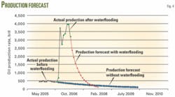
A cost-effective waterflooding plan allowed Khalda Petroleum Co. (an international joint-venture company) to improve oil recovery from the Tut field in Egypt’s western desert. With waterflooding, producing rates from the field increased to 4,000 bo/d up from 500 bo/d with primary recovery methods.
Considerations that the company took into account when planning a waterflood included:1
- Availability of low-cost water.
- Relative ease of injecting water.
- Horizontal and vertical sweep efficiency of the injected water.
- Oil-to-water mobility ratio.
- Displacement efficiency of the water.
- Cost of injecting water above the hydraulic head.
Waterflooding is a reliable and economic oil-recovery technique and operators have considered implementing waterflooding in almost all major oil fields in the world that do not have a natural water drive.2
Waterflood design
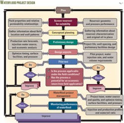
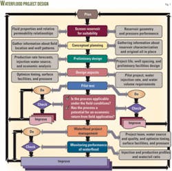
Fig. 1 shows the main steps for a waterflood design.
Reservoir factors to consider for waterflooding or pressure maintenance are:2
- Reservoir geometry.
- Lithology.
- Fluid properties and relative permeability relationships.
- Pressure performance.
Reservoir geometry (structure and stratigraphy) controls the location of the wells and, to a large extent, dictates the methods for producing a reservoir. Lithology influences the efficiency of the water injection. Lithological factors that affect floodability include porosity, permeability, and clay content.
Porosity directly relates to the total oil recovery from a reservoir.
Reservoir rock permeablity controls, to a large degree, the water injection that can be sustained for a specific sandface pressure. In determining the reservoir’s suitability for waterflooding, therefore, the design should determine the maximum permissible injection pressure for the depth. The evaluation requires extensive laboratory work and a comprehensive reservoir study. A pilot injection operation also can supplement the experimental data.
Physical properties of reservoir fluids also affect the waterflood design. Of major importance is oil viscosity that affects the mobility ratio. Another factor that affects the mobility ratio is the relative permeability of the reservoir rock to the displacing and displaced fluids.
The mobility ratio, M, is the ratio of the mobility of the displacing fluid to that of the displaced fluid. M should be less than one. The larger the mobility ratio, the lower will be the oil recovery at breakthrough; hence, more water must be produced to recover a fixed amount of oil. This is caused from a smaller area being swept at breakthrough and the larger stratification effects.
The reservoir pressure history is one of the most important factors to consider. The reservoir pressure in the waterflood should be held higher than the saturation pressure to maintain the pressure close to the initial pressure.
Other factors influencing the design are oil price, marketing conditions, operating expenses, water availability, legal considerations such as minimum spacing and adjacent leases, pattern selection, and process considerations such as injection rate, response time, production rate, flood life, and injector-to-producer ratio.
Waterflood patterns should provide sufficient water injection rates to:
- Yield the desired oil production rate.
- Maximize oil recovery with the least water production.
- Be compatible with existing well patterns and require few new wells.
Factors to consider in the conceptual planning are field location, reservoir shape, oil in-place, fluid saturations and distributions, reservoir characterization, zonal continuity, fractures and faults, formation dip, directional permeability, gas cap and aquifer size, previous reservoir development, gathering and separation facilities, production methods, production history, previous problems, and previous development studies.
The preliminary design provides such information as phase or full development, project life, initial oil rate, production rate forecasts, water injection rate, waterflood layout and well spacing, injection water source, produced water disposal plan, preliminary facilities design, capital and expense cost estimates, economic analysis, risk and mitigation plans, reservoir and well monitoring programs, and logistics and infrastructure considerations.
The design aspects include the determination of injection water source (quality, compatibility, and recycling produced water), water injection rate, optimum timing, optimum pressure level, fluid saturation at start of waterflooding, residual oil saturation at end of waterflooding, optimum well pattern, injection philosophy, injection well requirement, pilot project, and surface facilities.
A pilot test will determine if a process is applicable under the field conditions and if the process has a potential for an economic return from a field application.
The pilot test helps determine the recovery efficiency and provides a better understanding of the process mechanism as well as operational information on injection and production rates.
Waterflood management
Effective waterflood management requires a multidisciplinary team approach that includes reservoir, drilling, and production engineers, as well as chemists, accounting, legal, and others.
Guidelines for waterflood management include information on water source and quality. During most of the flood life, an oil reservoir will require about 0.5-1.0 b/d of injection water for each 1 acre-ft of reservoir volume. The ultimate volume of water required for many floods is about 1.5-2 times the reservoir pore volume.3 4
The water injected should be inexpensive and free from bacteria, suspended solids, and oxygen. It should also be nonreactive with any clays in the reservoir and compatible with the reservoir rock and formation water as well as not being corrosive in the injection and production facilities.
Injected water can include produced, surface, or subsurface water.4 5 The injection rate requirement to support the desired production rate depends on inflow performance relationship considerations, well injection pressure and rate, rules of thumb, local experience, and availability of compatible water.
Controllable parameters in a waterflood are the injection and production rates. Economic success depends on the additional recovery obtained and the cost of the water, injection wells, and surface treatment facilities.
Waterfloods require a regular analysis of the produced water to detect injected water breakthrough by such means as a change in chlorides if the injected and produced water have different salinities.
Other parameters to monitor are the presence of corrosive dissolved gases (CO2, H2S, O2); minerals, bacterial growth; dissolved solids; suspended solids, concentration and compositions; ion analysis; and pH. This data is gathered at the water source wells, water injection wells, and points in the injection system.
Tut field
The Tut field has proved to be a successful waterflood. The field is in southeast part of the Khalda concession in the north part of Egypt’s western desert. Discovered in 1986, the field currently has 21 oil producing wells and 3 water injection wells.
The field produces from the Alam El Bueib (AEB), Kharita, and Bahariya formations. The AEB-3D interval has two main sand bodies: upper and lower.
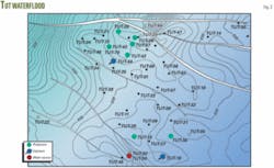
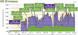
The interval is perforated and produces in most of the wells. Currently, AEB-3D has seven oil producing wells and two water injection wells. The zone produced under depletion drive until the recompletion of wells Tut-44 and Tut-19 as water injection wells in November 2006 and May 2007 (Fig. 2).
Volumetric estimates indicated that the zone had 13.6 million stock-tank bbl of original oil in place. As of November 2006, cumulative production from the zone was 2.5 million bbl, or 18% of the oil in place.
The operator expects the waterflooding of AEB-3D to increase the recovery factor to 35%, resulting in an ultimate oil recovery of 4.8 million bbl, or an incremental increased recovery of 2.3 million bbl from existing wells.
Until November 2006, the zone was producing 500 bo/d from two wells: Tut-41 and Tut-42. In addition, the field had several wells shut in because of low productivity caused by a lack of pressure support. On October 2006, estimated reservoir pressure of AEB-3D was 1,000 psig compared with 3,500 psig initially.
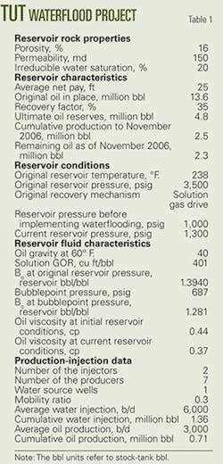
Table 1 shows the fluid and rock properties of AEB-3D.
Waterflooding in the AEB-3D zone of the nearby Qasr field had increased oil production from Well QSR-07 to 2,000 bo/d from 100 bo/d previously. Subsequently, Tut field well, Tut-44 in the AEB-3D, was recompleted as a AEB-3D water injection well. Injection in the well started on Nov. 27, 2006 at 5,000 b/d with zero wellhead pressure.
The injection led to production increasing to 4,000 bo/d from 500 bo/d previously (Fig. 3). The project involved recompleting wells Tut-70, Tut-67, and Tut-28 as well as upgrading the pumps in Tut-41, Tut-42, and Tut-28.
Less than 1 month after implementing water injection, the AEB-3D pressure recorded in Well Tut-67 was 1,300-1,500 psi in the lower sand compared with the initial 3,500-psi reservoir pressure.
Pressure data from well Tut-44 in the AEB-3D formation proved the well was in communication with the current producers Tut-41, Tut-42, Tut-70, Tut-76, and Tut-28. Therefore, Tut-44 was recompleted as water injection well and Tut-41, Tut-42, Tut-70, Tut-76, and Tut-28 were recompleted as oil producers to increase the recoverable reserves in the northwest area of the field.
The success in the northwest area led to the south area in the field being developed by recompleting Well Tut-19 as a water injection well, and Tut-15 and Tut-36 as oil producers. Figs. 3 and 4 show the production performance.
The selection of the injectors and producers in the northwest and south areas of the field was based on lower development costs through the use of less injection wells and for keeping the produced water to a minimum.
This waterflooding system is a closed system because the shut-in well, Tut-53, was converted into a water source well from AEB-3E. This well supplies injection water for the AEB-3D injectors: Tut-44, and Tut-19. A good practice is to use a closed system to reduce or eliminate water treatment. Well Tut-53 was good candidate for the water source from AEB-3E formation because the well has no other pay zone.
Tut-53 openhole logs showed a few feet of pay with low quality sand in AEB-3D formation and 25 ft of pay with good quality sand in Lower Baharia (LBAH) formation. Offset well Tut-45, 120 m away from Tut-53, had already drained the LBAH reserve in this area.
Acknowledgment
The authors thank Khalda Petroleum Co. for permission to publish this article.
References
- Forrest F.C., Reservoir Engineering Aspects of Waterflooding, SPE Monograph No 3, fourth printing, SPE, Richardson, Tex., January 1993.
- Thomas, C.E., Carroll F.M., George W.W., Petroleum Engineering Handbook, Chapter 44-Water-Injection Pressure Maintenance and Waterflood Processes, third printing, SPE, Richardson, Tex., February 1992.
- Thakur, M., “Surveillance Techniques- A Reservoir Management Approach,” JPT, October 1991.
- Rose, S.C., Buckwalter, J.F., and Woodhall, R., The Design Engineering Aspects of Waterflooding, SPE Monograph No 11, first printing, SPE, Richardson, Tex., 1989.
- Kornfeld, J.A., “Illinois’ Largest Waterflood Recovers Two Million Barrels in 25 Months,” OGJ waterflooding technical manual reprint, Petroleum Publishing Co., Tulsa, Aug. 4, 1952, pp 68-71 and 91-92.
The authors
Mahmoud Abu El Ela ([email protected]) is an assistant professor in the petroleum engineering department, Cairo University, and also works as a petroleum process consulting engineer at Khalda Petroleum Co. He previously worked as a research engineer at Woodside Research Foundation, Curtin University of Technology-Australia. Abu El Ela holds a BSc and MSc in petroleum engineering from Cairo University and a PhD from Curtin University of Technology. He is a member of the Egyptian Engineers Syndicate and SPE.
Ismail Mahgoub is chairman of Agiba Petroleum Co. He previously served as chairman for Khalda Petroleum Co., chairman for Petrozeit Co., operations general manager for Khalda Petroleum, assistant general manager for Wepco Petroleum Co., and associate professor for Cairo University. Mahgoub holds a BSc in petroleum engineering from Cairo University and a PhD from Institut National Polytechnique de Lorraine, France. He is a member in the Egyptian Engineers Syndicate and SPE.
