Solvent conversion at Canadian plant hikes sales gas, cuts CO2, S emissions
Shell Canada’s conversion of the sour-gas treating solvent at its Burnt Timber gas plant from a Sulfinol-D solution to methyl diethanolamine (MDEA) increased processed sales-gas volumes and heating value, improved sulfur-recovery-unit performance, and reduced CO2 and sulfur emissions.
The project was initiated primarily to offset the impact of higher CO2 concentrations forecast in the incoming raw gas and to increase plant capacity.
Higher CO2 content in the raw gas adversely affected the gas-treating unit as well as the sulfur-recovery unit.
MDEA was favored for its selectivity towards absorption of H2S over CO2 and the relatively low coabsorption of hydrocarbons.
Problems
Shell Canada’s Burnt Timber plant was originally designed to process sour gas with Sulfinol-D with two separate treating units: Plant 1 was built in 1970 with a capacity of 65 MMscfd and Plant 2 was built in 1976 with a capacity of 71 MMscfd.
The Sulfinol-D removed essentially all of the H2S and CO2 along with trace sulfur compounds such as COS and mercaptans. Acid gas from each treating united is routed to a dedicated sulfur-recovery unit.
Plant 1 has a two-stage Claus followed by a Superclaus, while Plant 2 has a three-stage Claus unit.
The plant’s license requires a current overall sulfur-recovery efficiency of 96.5%. The original feed to the plant came from Burnt Timber and Panther fields, had a low condensate-to-gas ratio, and contained about 12% H2S and 7% CO2. The acid-gas stream going to the sulfur-recovery units was more than 60% H2S and contained 1.3% to 2.5% hydrocarbons on a methane-equivalent basis. About half of the equivalent hydrocarbon consisted of benzene and toluene.
The hydrocarbon content in the acid gas resulted in several problems. The first problem was the consumption of air to combust the hydrocarbons. Sulfur-plant capacity was often limited because the main air valve would open to 90% and control of the air would become difficult. The sulfur plant usually limited overall plant throughput.
The second problem with the hydrocarbons was the production of CS2 in the reaction furnace. Levels of CS2 as high as 1.25 % in the feed to the first Claus stage were measured. Hydrolysis rates of 90% of the CS2 in the first bed were achievable with new catalyst, but the remaining CS2 still had a significant impact on the overall sulfur recovery.
The third problem with the hydrocarbon was that it was not all completely combusted in the reaction furnace. The residence time of 0.5 sec with a reaction furnace temperature of 1,100° C. resulted in breakthrough of benzene to the first converter bed. This benzene cracks in the converter bed resulting in soot deposition on the Claus catalyst. Sooting of the bed reduced catalyst activity and resulted in increased pressure drop, reducing recovery efficiency and capacity.
Catalyst in the first bed of Sulfur Plant 2 was being changed every 6 to 9 months resulting in excessive operating costs and lost production.
The CO2 in the acid gas was less of a problem than the hydrocarbons but did exacerbate the previously outlined problems. The inert CO2 increases the pressure drop through the unit and hence backs the blowers up on their operating curves. The CO2 in the acid-gas feed results in production of COS in the reaction furnace, reducing the overall sulfur recovery. Finally, the CO2 reduces the reaction furnace’s flame temperature, increasing the breakthrough of benzene to the first reactor bed.
The two main fields connected to the Burnt Timber facility have different gas compositions and different production profiles. The Burnt Timber field has H2S and CO2 contents of 10.2% and 6.4%, respectively. The Panther field on the other hand has H2S and CO2 contents of 7.0% and 11.5%, respectively.
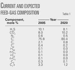
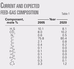
With the Burnt Timber field in decline and additional drilling in the Panther field, the forecast composition for the plant inlet was that the H2S content would decline while the CO2 content would increase. Table 1 gives the current and future feed-gas compositions.
This change in composition would result in deterioration in sulfur-plant performance due to a less favorable H2S/CO2 ratio in the acid gas. In addition, because the active amine in Sulfinol-D is di-isopropanolamine (DIPA), the increasing CO2 content increases the equivalent rich solvent loading faster than the declining H2S content decreases the loading.
In order to maintain a constant equivalent rich loading, the solvent/feed-gas ratio would need to increase. Higher solvent-to-feed-gas ratio would increase the hydrocarbon co-absorption resulting in increased hydrocarbon in the acid gas, deteriorating sulfur-plant performance and plant capacity even further. Fixed charge-pump capacity would also mean that gas throughput would have to be reduced as the CO2/H2S ratio increased.
An additional factor was the overall sulfur-recovery efficiency. The Burnt Timber plant was grandfathered when the regulating authority introduced new higher efficiency sulfur-recovery guidelines. Grandfathering allows the plant to build sulfur-recovery credits, which can defer a capital expenditure for a tail gas clean-up unit.
Credits can only be built, however, if sulfur-recovery efficiency is sufficiently high. Predicted efficiency with Sulfinol-D acid gas indicated that sufficient credits could not be built, which would accelerate the need for a tail-gas unit.
The direction of the gas composition, current capacity constraints, poor sulfur-plant performance, and shortened catalyst life showed a need to improve the H2S selectivity of the treating units, reduce the hydrocarbon content of the acid gas, and increase overall plant capacity.
A feasibility study conducted by Millenia Resource Consulting, Calgary, showed that a solvent swap from Sulfinol-D to MDEA would provide these benefits, and detailed study work was initiated with Shell Global Solutions, Houston, to evaluate such a swap.
Shell’s models for absorbers simulate using actual number of trays and calculate the mass transfer rates on each tray. Operation to slip enough CO2 to give 3.8% CO2 in the treated gas from the MDEA was targeted, as this would allow the blend of gas from Trains 1 and 2 to meet the 2% CO2 specification for the sales gas to the pipeline with Train 1 remaining on Sulfinol-D.
An additional reason to consider a solvent swap in only Plant 2 was that the feed gas contains COS and mercaptans that are effectively removed by the Sulfinol-D but would not be removed as well by MDEA.
The accompanying box shows treated-gas sulfur specifications, trace sulfur compounds in the feed gas, measured trace sulfur compounds in the treated gas from the Sulfinol unit, and predicted trace sulfur compounds in the treated gas from an MDEA absorber operating to give CO2 slip.
The numbers in this box make clear that MDEA is expected barely to meet the total sulfur specification, but operating a facility so close to specification is undesirable. By keeping Train 1 on Sulfinol-D and blending the treated gases, operators expected combined sales gas to have a total sulfur content at about half of the specification. If required to operate only Train 2, they could use a higher solvent/gas ratio and the lean solvent feed location to increase both CO2 and trace sulfur-removal rates.
The results of the study indicated that conversion of Plant 2 was technically possible. The economics of the project, based on increased capacity, higher sales-gas heating value, and improved sulfur-plant performance were favorable.
Original configuration
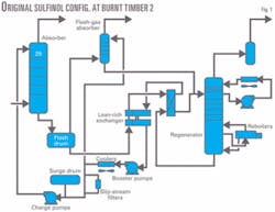
The original plant configuration was of a typical Sulfinol unit (Fig. 1).
The absorber column contained 29 conventional two-pass trays and operated at a pressure of 5,800 kPa(g). Lean Sulfinol was supplied at 40° C. and the main charge pumps were capable of supplying 227 cu m/hr. Flash gases from the rich Sulfinol flash drum were treated in a flash-gas absorber.
The lean-rich exchangers consisted of the original shell and tube exchangers supplemented with a plate and frame exchanger installed during debottlenecking. The regenerator column contained 22 Shell HiFi calming-section trays in the stripping section, and seven calming-section trays in the reflux-cooling section. An internal reflux-cooling system, in which reflux water is pumped around and cooled was provided.
Two reboilers operating on 350 kPa(g) steam provide the duty for stripping. A booster pump downstream of the lean-rich exchangers provides enough pressure to flow the Sulfinol through the lean-solvent cooler, solvent filter, and to the fuel-gas absorber. The charge pump supplies cooled Sulfinol to the absorber.
Modifications for conversion
The initial project study was based on equipment capacities that had been identified in a performance test conducted in 1999. There was a desire to use as much existing equipment as possible while ensuring that it was in good shape. In addition, Shell Canada wanted to incorporate its experience with operation of two existing MDEA units to ensure long trouble-free operation.
The company passed the process design developed by Shell Global Solutions to Millenia Resource for detailed design and construction.
Solvent pumps; absorber
Both booster pumps and charge pumps had nearly the maximum impellers installed, and Shell Canada decided to use the existing pumps without modifications. Additional solvent flow would not improve capacity because other equipment limits would restrict capacity first. The design was advanced with the booster pump flow of 259 cu m/hr and a charge pump flow of 227 cu m/hr.
The most complex part of the modifications was in the absorber tower. Its design had to account for the change in the H2S/CO2 ratio in the feed gas over time. Slip of up to 4% CO2 in the treated gas was desired while achieving no more than 8 ppm (vol) of H2S.
Because the process design was to use kinetic selectivity to obtain the desired slip, a weir height of 50 mm was selected for design. Calculations indicated that 22 trays would be required to obtain 2% CO2 in the treated gas for the composition expected in 2020, while 14 trays would achieve less than 8 ppm (vol) H2S for all gas compositions.
The uncertainty in gas composition and the parameters required for calculations involving kinetic slip prompted a decision to provide the absorber with multiple liquid feeds. Although this would require addition of nozzles on the existing absorber, it would also provide the flexibility to handle most of the uncertainties.
Feed locations at tray Nos. 12, 14, 16, and 22 were selected. The tower would be retrayed from the top down, so that the new Tray 22 would be in the same location as old Tray 29 and would use the existing feed nozzle.
The space for the new feed nozzles would be created by omitting the tray that was in that position. The new Tray 1 would end up where the existing Tray 5 was, providing more room in the absorber sump. The normal liquid level in the sump would be increased to provide more residence time for gas de-entrainment.
As previously pointed out, the existing absorber had conventional two-pass trays installed for the Sulfinol service. When swapping to MDEA it is generally recognized that the system foam factor will increase.
In addition, Shell tray design parameters for MDEA are more conservative than parameters for Sulfinol systems. When the hydraulic calculations were made for the existing trays in MDEA service, many of the design parameters exceeded acceptable values. A switch to Shell HiFi calming-section trays provided a tray design that would meet the more stringent design conditions for the MDEA solvent.
Shell Canada’s experience with the MDEA units at Caroline prompted a review of the materials of construction. The expected maximum rich MDEA loading of 0.80 mole/mole resulted in the recommendation that the bottom section of the absorber be strip lined with stainless steel.
Materials engineers felt that strip lining from Tray 6 down would eliminate any problems with corrosion associated with rich loading of MDEA now and in the future.
Flash drum, absorber
The existing flash drum had hydrogen blistering and was showing signs of corrosion, particularly along the gas-liquid interface. It was decided to replace the existing flash drum with a stainless steel vessel to provide 5 min of liquid residence time.
An integral flash-gas absorber also of stainless steel was added to the top of the flash drum. It was only 457 mm in diameter compared to the original diameter of 610 mm. Given the new smaller diameter, the column was packed with 5 m of No. 2 Cascade mini rings.
The reduction in size reflects the expected decrease in the amount of flash gas. The MDEA solution was expected to have about one third of the dissolved hydrocarbons compared to Sulfinol, and the additional residence time in the sump of the absorber was expected to reduce the entrained gas level.
Lean-rich exchangers
The new design duty for the lean-rich exchangers of 6,675 kw was provided by two 100% plate and frame exchangers. The clean duty of each exchanger was about 8,000 kw.
The exchangers were configured for both series and parallel operation to allow for cleaning one unit without a drop in throughput and for tighter temperature approach with the exchangers in series. The pressure profile on the lean side was controlling, as sufficient head was required at the solvent booster pump.
Regenerator; reboilers
The stripping section of the regenerator was previously fitted with 22 Shell HiFi calming-section trays, high capacity trays with limited scope for debottlenecking. The column was re-rated to account for the increased foaming tendency of MDEA relative to Sulfinol.
Although some of the design parameters were higher than desirable for a new design, they fell within acceptable limits for retrofit applications. Shell Canada felt that the regenerator flooding might become the new plant limit, but that would depend on the capacity limit of the regenerator reboilers. The inlet feed nozzle and the rich-feed zone, one tray above and one tray below the inlet nozzle of the regenerator, were strip lined with stainless steel.
The two existing regenerator reboilers have a design duty of 12,600 kw, with the required new duty being 13,100 kw. Because performance testing indicated that the reboilers had operated at 13,000 kw previously, reboiler duty was not considered a bottleneck for the design case.
Total plant throughput might be limited in the future by the ultimate reboiler duty achievable. Metallurgy was upgraded on the reboiler feeds, overheads, and liquid returns. The reboiler vapor space had been metal sprayed in a previous turnaround and the exiting reboiler bundles were stainless steel.
Solvent coolers, filters
The lean solvent cooler actually consisted of three aerial coolers that had been valved to run in a series-parallel combination. The design duty was 9,660 kw, with the required new duty being 8,300 kw.
The piping was modified to allow the two smaller coolers to run in series with the larger third cooler to improve cooling during the summer.
The Sulfinol system had existing full-flow particle filtration. With the swap to MDEA, activated-carbon filtration was added along with post-carbon-bed particle filtration. Capacity of the carbon bed was 5% of the solvent flow.
Inlet filter coalescer
The original inlet flow to the plant was relatively low in liquids and the original inlet separators were not overly large. During operation of the Sulfinol unit, numerous incidents occurred when the inlet slug catcher became overloaded and passed liquid to the treating unit. An inline cyclone separator existed but had limited effectiveness in slug situations. This resulted in liquid hydrocarbon and salt water entering the Sulfinol unit.
MDEA being more susceptible to foaming due to liquid hydrocarbons led to a decision to install a filter coalescer between the inlet slug catcher and the absorber. The model selected had a lower chamber to catch bulk liquid and an upper chamber with the coalescing elements. Each chamber had separate level controls.
Inlet feed-gas preheater
Two theories existed in order to maximize the selectivity of the MDEA. One was to keep the inlet gas temperature low and the other had evidence that higher temperatures would be required to obtain the desired selectivity.
Although the arguments for the feed preheater were not compelling, a suitable heat exchanger was available as surplus and was installed. Preheat of the feed gas would be provided by cooling of the treated gas, which would offload the propane refrigeration system.
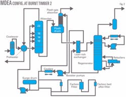
Fig. 2 shows the flow for the plant reconfigured for MDEA.
Predicted performance
Process models and design experience helped predict the performance of the sweetening unit with MDEA. The design investigated the impacts of solvent strength, number of trays, lean solvent temperature, and feed-gas temperature and composition. Shell Canada selected a solvent strength of 45 wt % to balance acid gas pick-up and solvent temperature rise.
Lean solvent loadings of 0.0028 mole/mole for H2S and 0.0045 mole/mole for CO2 were used based on the expected performance of the regenerator. The base feed-gas conditions were 22° C. and 5,752 kPa(a) and the base lean solvent temperature was 40° C.
CO2, H2S removal
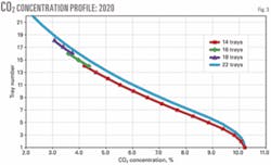
Fig. 3 presents the CO2 profile in the absorber for base operating conditions in 2020 for various tray counts. The graph shows the complete profiles for 14 and 22 trays and only the last three trays for the 16 and 18-tray cases.
Note that the profiles indicate that the absorber is operating in kinetic selectivity as the CO2 concentration is continuously decreasing with increasing tray number. Operation with 22 trays results in slightly more than 2% CO2 in the treated gas, while operation with 14 trays results in just more than 4% CO2.
A similar plot for the feed-gas composition in 2005 results in treated-gas CO2 contents of 1.5% and 3% for 22 and 14 trays, respectively. These data suggest that a minimum of 16 trays is required in 2020, while fewer than 14 trays are required now to meet the CO2 slip criteria of 4%.
Fig. 4 presents the H2S concentration vs. number of trays for two different gas compositions. Note that the conditions for the graph are solvent at 40° C. and a lean H2S loading of 0.0028 mole/mole. Because it is possible to cool to less than 40° C. in the winter, H2S removal could be improved.
Achieving lean MDEA loadings of less than 0.0028 mole/mole may also be possible, but the increased stripping steam may overload the regenerator. The minimum number of trays to achieve 8 ppm (vol) in 2020 is 16, while slightly more than 14 trays are required in 2005. Over circulation or additional stripping would reduce the number of required trays.
Calculations were also done at a lean solvent temperature of 50° C. The calculated H2S in the treated gas was found to be 13 ppm (vol), too high for the required specification. Because the equilibrium H2S concentration at these operating conditions was found to be 8 ppm (vol), even with 22 trays it would be difficult to make the 8 ppm (vol) specification.
Absorber temperature
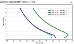
Temperature profiles for various operating conditions were also determined (Fig. 5).
The profiles clearly indicate that the energy balance is dominated by the liquid stream, as warming the gas from 22° C. to 35° C. only shifts the lowest part of the profile by 2-3° C. Increasing the lean solvent’s temperature by 10° C. shifts the entire profile by 10° C.
When all of the design calculations provided results that were similar to those reported by Weiland and Dingman,2 Shell Canada was confident with the predicted performance of the unit.
Construction
Construction was fast tracked due to time constraints and resulted in short windows for equipment delivery. The construction premise was to have the majority of the new equipment, piping, and structural completed before the scheduled plant shutdown. Work during the shutdown was to be limited to vessel work, final tie-ins, and inspection of existing equipment.
Most of the equipment was on three skids: the gas-gas exchanger and coalescer skid, lean-rich exchanger skid, and the flash tank skid. Problems at the fabrication shops for the flash tank and gas-gas exchanger skids delayed deliveries of the skids. The added work in the turnaround scope increased costs and extended construction times.
The major work undertaken during the shutdown was the installation of three feed nozzles on the absorber, modification or removal of the tray rings, and strip lining of the lower 10 m of the absorber with stainless steel and bush lining of the nozzles.
This work was done with one contractor that was able to section off the tower into three areas so that three crews could work simultaneously. The areas of the towers that required welding were preceded with a hydrogen bake out for 16 hr, continuous weld preheat, followed by stress relieving of the new nozzles.
Installation of the new trays went well considering that the tray rings had to be converted from partial rings to full rings in order to support the Shell HiFi trays. Tray ring extensions were welded into place to ensure tray sealing. During installation of the first few trays, it became apparent that an error had been made in the tray drawings: The bottom collector tray had been fabricated to take flow from an “odd” tray. Although tray installation continued with an “odd” tray, this meant that there was an extra even tray and an odd tray was missing.
The tray fabricator was able to build the required tray on short notice and the vessel contractor was able to modify the liquid distributor piping for each feed point resulting in a small schedule impact.
Commissioning
One of the most difficult aspects of commissioning was getting the system clean after all the work in the absorber. The absorber and regenerator were first vacuumed to remove as much grit and welding slag as possible. The vessels and piping were purged free of air and gross-leak tested with nitrogen supplied from bulk transport trucks. A final leak check was then done at operating pressure using sweet fuel gas.
The magnitude of piping replacement and vessel work required for construction of the project made it necessary to flush the system before start-up to remove chemical and construction debris.
Start-up strainers were installed on the suction side of the booster pumps and the charge pumps to prevent equipment damage and to aid in removal of debris. Filters (50μ nominal) were also installed in the full-flow filter vessel to further help clean the system.
The system was then charged with steam condensate until sufficient operating levels were established. Normal circulation was established with the exception that the lean-rich exchangers were bypassed to prevent damage. All pumps and filters were closely monitored for cavitation and plugging and screens and filters were replaced as required. The booster pump suction screens plugged numerous times indicating a large amount of debris was left behind from the vessel work in the regenerator.
The steam condensate temperature was progressively raised to 60° C. A degreasing solution was then added to the system via a pressure truck. The solution consisted of 1.0% soda ash, 1.0% trisodium phosphate, and 0.2% surfactant. The solution was circulated according to contractor recommendations.
The system was then drained completely and recharged with fresh steam condensate. The lean-rich exchangers were commissioned and steam condensate was circulated for 3 hr at 3,000 cu m/day to achieve three full circulations. The system was then drained and charged with a 50:50 MDEA/water mixture.
Start-up
Normal plant start-up practices were followed, and gas was introduced without unexpected issues or upsets. Once the lean-rich exchangers were placed in series configuration on the lean side, however, cavitation of the booster pumps occurred at circulation rates greater than 3,500 cu m/day. This cavitation resulted in damage to the mechanical seals on the pumps and required a complete unit shutdown of 3 days for delivery of replacement parts.
Once the seals were replaced and the system was returned to operation, plugging occurred in the absorber level’s control valve. The manual bypass valve could not be used effectively due to high vibration; therefore a system shutdown was again required for removal of debris (welding slag, bolts, etc) from the valve trim. This issue occurred three more times with the same result. Bypass piping was then added with a redundant level-control valve installed with a different style trim.
Even though the lean-rich exchangers were only put in service after the system was cleaned, they did experience fouling in the early stages of MDEA circulation. Fouling led to pulsation in the exchangers and difficulty in controlling the still temperature. The exchangers had to be cleaned on line several times.
Optimization, operation
Once the solvent cleaned up, we conducted a series of tests to check the performance of the unit against the design. Feed tray location was varied, the maximum gas rate was determined, and steam and solvent to gas rates were varied. The key results from these tests are presented below.
CO2 slip
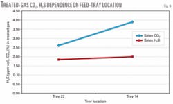
Fig. 6 shows the impact of feed tray location on the CO2 and H2S content of the treated gas. Note that the amine circulation rate and raw gas H2S, CO2 concentration are similar for both cases.
Performance results
The maximum gas rate achieved during the performance test was 2.05 million cu m/day. The bottleneck was the sulfur plant in all tests completed. This value exceeded the design value of 1.8 million cu m/day.
One of the key benefits of the solvent swap has been a reduction in the steam demand for gas treating. Although the MDEA unit requires about 25% more steam for each cubic meter of solvent, the solvent flow required for each cubic meter of raw gas is about 60 % less. The net result is that per volume of raw gas the MDEA unit consumes 25% less steam than the Sulfinol unit. Part of this is the result of less CO2 pick-up due to slip, while part is due to the higher CO2 capacity of the MDEA.
Another benefit of the conversion to MDEA has been the drastic reduction in flash gases from the flash tank. The flash gases are sweetened in the flash gas absorber and are used in the plant as wet fuel gas. The flash gas flow during the Sulfinol operation was often greater than 30,000 cu m/day. This resulted in a surplus of wet fuel gas for the plant necessitating the flaring of the excess. The MDEA only produces 2,000-4,000 cu m/day of flash gases.
The conversion to MDEA in Plant 2 at the Burnt Timber gas plant has been very successful and has met all of the objectives for the project. Plant 2 currently slips up to 4% CO2 to sales, which has resulted in a combined sales-gas CO2 content of 2%.
The MDEA operates well with very few upsets and next to no foaming. This can be attributed to a combination of things. One is the fact that the inlet coalescer collects a considerable amount of hydrocarbon, which prevents it from entering the gas-treating unit where it otherwise would contaminate the MDEA and cause foaming. The carbon filter also removes any contaminants that do get into the system.
The carbon filter is not in continuous operation and is put into service to clean up the MDEA when required. The full-flow filters that were installed before the MDEA conversion also help to keep the solution clean. All these factors have resulted in a relatively trouble-free amine system with few foaming incidents.
The CO2 slip has also increased the acid-gas quality to as high as 70% H2S from 58%, depending upon inlet-gas composition. The hydrocarbon content has dropped from greater than 2.5% to less than 1% on a methane-equivalent basis. As a result the COS content in the feed to the first Claus stage has dropped from as high as 1.25% to about 0.23%.
The lower hydrocarbon content in the acid gas has resulted in decreased sooting of the first Claus bed leading to longer bed life and increased CS2 and COS hydrolysis. The total reduced sulfur (TRS) emitted to atmosphere from the incinerator stack has also decreased dramatically.
The COS and CS2 concentrations in the stack have dropped to 50 and 16 ppm (vol), respectively, from about 130 and 200 ppm (vol). The total TRS concentration has dropped to 100 ppm (vol) from 600 ppm (vol). These improvements have resulted in an increase in sulfur recovery in Plant 2 to 96.9% from 95%.
One concern in converting from Sulfinol to MDEA was the removal of trace sulfur compounds. The design calculations indicated COS and mercaptan removals of 28% and 37%, respectively. A test on Oct. 13, 2006, with feed to Tray 14 indicated actual COS and mercaptan removals of 26% and 47%, respectively, with H2S in the treated gas of 2.7 ppm (vol).
Testing of Plant 1, operating on Sulfinol, showed removal of COS and mercaptans of 85% and 80%, respectively, and 1.3 ppm (vol) of H2S in the treated gas. The inlet gas at the time contained 112 mg/std. cu m of trace sulfur compounds compared to the design value of 117 mg/std. cu m. Under these conditions, the total sulfur content of the combined sales-gas stream was 59 mg/std. cu m, easily meeting the specification of 115 mg/std. cu m.
Unfortunately, a subsequent test on Oct. 25 showed COS and mercaptan removal rates of 8% and 15%, respectively, with an inlet gas trace sulfur content of 199 mg/std. cu m. The total sulfur content of the combined sales-gas stream was measured at 141 mg/std. cu m. This problem is being investigated by technical staff.
It was determined that field activities related to sulfur-solvent washes of production tubing resulted in the high levels of trace sulfur compounds in the inlet gas. Operational plans are being put in place to limit the concentration of mercaptans in the feed gas during these field activities.
References
- Gupta, Lily, and McGillicutty, Patrick, “Burnt Timber Gas Plant 2 MDEA Conversion Study, November 2004,” internal design report.
- Weiland, Ralph H., and Dingman, John C. (2002), “Simulator provides Guidance for Increasing CO2 Slip in Gas Treating Applications,” Gas Processing, Winter, pp. 21-28.
The authors
Ken Sourisseau ([email protected]) is an adviser and coordinator, process engineering (E&P), at Shell Canada Energy. Ken has worked for Shell in Canada, Abu Dhabi, and The Netherlands in a variety of technical and operations positions, associated with sour gas treating and heavy oil production. He also teaches a course in gas processing at the University of Calgary. Sourisseau holds a BSc (1976) in chemical engineering from the University of Saskatchewan and an MSc (1978) in chemical engineering from the University of Minnesota. He is a registered professional engineer in Alberta and a member of GPA Canada and the Canadian Heavy Oil Association.
Jamie Grant ([email protected]) is an operations engineer at Shell Canada Burnt Timber gas plant. He has also worked at the Caroline gas complex for Shell Canada as a process engineer. Grant holds a BSc (2002) in chemical engineering from the University of New Brunswick and is registered professional engineer in Alberta.
Mark Weiss ([email protected]) is currently project lead for the operations integrity assurance department of Shell Canada Energy. As a power engineer he has operating and facility start-up experience associated with sour-gas production facilities.
