Method determines axial force in subsea pipelines
A new method allows for determination of axial force on subsea pipelines within the context of DNV-RP-F105-2006, expanding the scope of current recommended practices and benefiting both project economics and safety.
Existing recommended practices for free span analysis do not address how to determine axial force in subsea pipelines, except for theoretical simplified conditions of axially completely unrestrained or totally restrained pipe. As a result, the designer often uses the totally restrained value to be conservative.
Axial force plays an especially important role in pipelines operated at higher pressures and temperatures. HPHT conditions result in a higher axial force and through this higher longitudinal stresses, which affect allowable free span lengths. Determination of actual axial force therefore affects the economics of a pipeline project.
Effective axial force governs static analysis, including determination of stresses and natural frequency. It depends on operating parameters such as pressure, temperature, pipeline deflection, and soil restriction.
Seabed unevenness, change of seabed topology, strudel scours, and artificial supports required for existing pipeline crossings can all lead to free spans in subsea pipelines. Assessment of free span requires structural (static) analysis.
This article provides guidance within the development of DNV RP-F105-2006 for assessment of pipeline free spans based on design criteria.
Background
For a single span, an analytical solution procedure to estimate axial forces caused by high pressure and high temperature differentials considers pipeline longitudinal movement (sliding) and transverse deflection.1 It also considers the soil resistance at the shoulder of the span, nonlinear relations between strain and deflection, and the thermoelasticity relationship between strain and load effects.
A displacement balance equation for the shoulder and the free span tie-in point yields the effective axial force. The bending moment caused by the transverse load and axial force adjusts the geometrical nonlinearity.
The proposed method allows the determination of stress parameters required by DNV-RP-F105, including the fundamental natural frequency. This article presents the calculation procedure using MathCAD software and an example with input and detailed output data.
Results are comparable to finite-element-method results for similar boundary conditions and assumptions.
The proposed method provides an economic design solution and enhances the reliability of the pipeline.
Basic assumption
This article’s basic assumptions coincide with the realistic characterization of the cross-sectional behavior of a pipeline.1 The equations’ bending stiffness coincides with that of concrete coated steel pipe.
This article, however, does not consider changes in the concrete-coated pipe’s bending stiffness caused by bending moments (OGJ, June 19, 2006, p. 53) and assumes the steel pipe’s material linearity (OGJ, June 22, 1998, p. 72). Linear transverse and longitudinal stiffness modeled pipe-soil interaction. Recommended practice may determine the values of the concrete-coated pipe’s stiffness and the soil stiffness.1
Soil resistance and relaxation due to pipeline displacement determine the effective axial force caused by pressure and temperature differentials. Timoshenko’s method addressed so-called geometrical stiffness, governed by the effective axial force.2 The determination of pipeline configuration due to transverse load (submerged weight of the pipe in vertical direction or drag loading in horizontal direction) provides the basis for this method, prior to analyzing the pipeline with initial displacement due to lateral force.
Transverse load
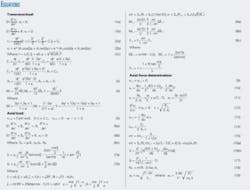
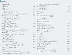
Equation 1 provides classical equilibrium in terms of transverse displacement (v) for the free span (subscript 1) and the shoulder (subscript 2), based on the soil resistance model assumption (see accompanying equation box). The solutions of these differential equations (Equation 2) include eight arbitrary constants determined from two shoulder boundary conditions, four free span and shoulder conditions of conjunction, and two midspan symmetrical conditions. Equation 3 presents the eight determined constants.
Equation 4 shows the bending moments (M) and deflections (f) at the middle (ζ = 1) and ends (ζ = 0) of the span, based on Equation 2 and the values of constants in Equation 3.
These equations for bending moments and deflection used the known formulas for a single pipeline span with both fixed ends multiplied by soil stiffness parameters.
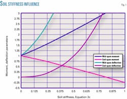
Fig. 1 illustrates the relationship of moments and deflection parameters with vertical soil stiffness parameter φ. The solution for bending moments and deflections for fixed ends (φ = 0) agrees with the ordinary solution. The bending moment at the span ends, which is twice as large as the midspan moment for the fixed-end condition, uses a soil-stiffness reduction, while the moment at the midspan increases with soil stiffness reduction, and may be greater than that at the end-span.
Axial load
The combined effect of transverse and axial loads may lend itself to interpretation as a pipeline with initial deflection caused by transverse load exposure only to axial force. Equation 5 describes the initial configuration of free span pipelines with satisfactory accuracy for engineering purposes.
Equation 6 presents the equilibrium equations for the free span with initial deflection and the shoulder with resistance soil model due to effective axial force. Equation 6c describes the effective axial force, which is positive in compression.
After determination of the arbitrary constants from the boundary conditions, the solutions of the above differential equations (Equation 7) describe the deflection of the free span and the shoulder. Equation 7 uses dimensionless parameters of the effective axial force; the ratio of the effective axial force to the Euler critical buckling force for the pipeline with fixed ends and to the critical buckling load for the infinite pipeline with linear soil stiffness.
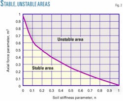
As follows from Equation 7, the value of parameter λ = 0 defines buckling.
Fig. 2 represents the area of stable equilibrium.
Since a value of zero for parameter n defines the fully fixed ends, the soil stiffness is reduced as n increases from zero, reducing the critical force along with it.
Equation 8 defines bending moments M and deflections f at the middle (ζ = 1) and ends (ζ = 0) of the span. Equation 8 stems from Equation 7 which describes the pipeline deflections. These equations also represent the known formulas for a single pipeline span with both fixed ends multiplied by soil stiffness parameters.
The bending moment at midspan, caused by the compressive effective axial force, increases with soil stiffness reduction. The bending moments at the span ends diminish if this axial force is less than the Euler critical force for a span with both fixed ends, but increase if the axial force is more than the Euler force for the same soil stiffness.
Force determination
The effective axial force equals the true steel-wall axial force with correction for the effect of internal and external pressures shown in Equation 6c. The unknown true steel-wall axial force depends primarily on temperature differentials and pressure that can be determined from the continuity equation of the longitudinal displacement at the end of span described by Equation 9.
The nonlinear relation between the strain, displacement, and deflection (Equation 10) and the thermoelasticity relationship between strain and load effects (Equation 11) can determine longitudinal displacement at the ends of the span from the free-span portion. The equilibrium condition of the shoulder line with soil stiffness in the longitudinal direction Kx (Equation 12) can determine the longitudinal displacement of the shoulder ends.
Calculating displacement components in Equation 9 in accordance with Equations 13 and 14 allows rewriting it as Equation 15. Solving nonlinear Equation 15 allows determination of the parameter of effective axial force, m.
MathCAD can solve this essentially nonlinear equation. MathCAD software provides for the numerical integration required to solve Equation 15.
The special case when both ends of a free span are fully fixed can illustrate the fundamental features of Equation 15. Equation 17 shows the integral in Equation 16 written in closed form.
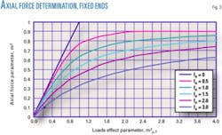
Fig. 3, based on Equations 15 and 17, shows the parameter of axial force for a free span with fixed ends vs. the pressure and temperature differential. This result plays an important role in qualitative assessment. Axial force caused by pressure and temperature effects cannot exceed the critical force of the span with initial deflection, the ratio of axial force to critical force (m2) tending to one.
Solving Equation 15 also allows determination of the fundamental natural frequency taking boundary conditions into account.
Ratios of natural frequencies in pipelines with different boundary conditions are proportional to the square roots of their corresponding static deflections. Equation 19, therefore, determines the fundamental natural frequency adjusted for the axial force, which in turn is based on the classical solution for pipelines with fixed ends as well as the parameters of deflection for a free span shown in Equations 4 and 8c.
Design application
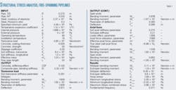
The described method can determine free-span structural analysis parameters such as bending moments, axial force, deflections, and the fundamental natural frequency required by DNV-RP-F-105. Data for a typical 10-in. offshore high pressure-high temperature (2,300 psig, 180° F.) pipeline illustrate the application of this new method.
Table 1 presents results of calculations (output) performed by the MathCAD program developed for this condition. MathCAD’s ability to conduct the numerical integration required for the calculation procedure led to its selection.
DNV-RP-F-105 paragraph 6.2.5 provides the basis for calculating the stiffening effect of the concrete coating,1 with the soil transverse and axial stiffness parameters calculated according to Equations 2c and 12.
Equation 4 then provides the basis for calculating the bending moments and deflections at the ends and midspan due to transverse load. Nonlinear Equation 15 then calculates the effective axial force using the deflection from transverse and axial loads according to Equation 7, the axial force relaxation according to Equation 16b, and load effect parameter according to Equation 16a. Equation 19 determines the true steel-wall axial force once the parameter of effective axial force is known.
Total bending moments determine maximum-minimum longitudinal stresses due to the transverse load according to Equation 4 and axial load according to Equation 8, as well as the true steel wall axial force according to Equation 19.
The Von Mises combined stress, which considers longitudinal and hoop stresses (according to Equation 11), may act as one of the criteria for allowable free span assessment. Effective axial force determines the fundamental natural frequency (first Eigen frequency) according to Equation 19, which also considers boundary conditions.
The proposed method can be applied to the provisions of the DNV Codes and allows inclusion of stress analyses required for free span assessments of HPHT pipelines.
References
- DNV-RP-F105 “Free Spanning Pipelines,” Det Norske Veritas, p. 45, 2006.
- S. Timoshenko, “Strength of Materials,” New York: Kriegas, Huntington, p. 247, 1976.
The author
Alexander Aynbinder ([email protected]) is a research engineer and scientist. The companies he has worked for include J. Ray McDermott, Gulf Interstate Engineering, and Fluor Daniel. Before immigrating to the US (1990), Aynbinder was a lead research scientist in the Russian State Research Institute for Pipeline Construction (VNIIST). He is a graduate of the Moscow Civil Engineering University and received a PhD in civil engineering (1977) from the Central Research Institute of Civil Structures in Moscow. Aynbinder’s major research interest is stress analysis of offshore-onshore pipeline-piping systems.
