SPECIAL REPORT: SAKHALIN RMR-1: Elvary Neftegaz plans riserless system for Sakhalin drilling program
In 2006, CJSC Elvary Neftegaz deployed a riserless mud-recovery (RMR) system off Sakhalin Island.
An RMR system enables dual-gradient subsea drilling operations to take place with the well open at the seabed. There are no pressure-containment devices at the wellhead, but as with earlier systems developed for deepwater drilling, mud and cuttings are returned to the rig by a subsea pumping system, fluid recovery hose, and umbilical.1 The system was field tested as part of the Norwegian DEMO2000 project.2 Subsequently, it was used in a multiwell drilling campaign in the Caspian Sea.
This two-part series describes how the riserless mud-recovery system was implemented in a remote exploration drilling operation off Sakhalin Island. The first part covers project planning and engineering. The concluding part, to be published May 7, discusses the RMR system installation and operation.
After the company’s Sakhalin experiences in 2004-05, a clear business case emerged with the underlying drivers of limited weather window, shallow gas, and stringent discharge regulations.3
Accordingly, a formal project was established and several critical risk-reduction studies were carried out in relation to shallow gas and integrity of the return hose under high current conditions. Correct interfacing aboard the rig required careful choice of location, power supply, wellhead, and remotely operated subsea vehicle. There, changes were verified by means of a formal hazard and operability review.
A significant part of the effort involved gaining certification of the equipment for use in the Russian Federation in parallel with fabrication, acceptance testing, mobilization, offshore installation, and commissioning of the system. The article concludes with a review of operational experience from the 2006 drilling season along with associated lessons learned and forward plan.
Sakhalin shelf
CJSC Elvary Neftegaz, a joint venture between OAO Rosneft and BP Exploration Operating Co. Ltd., drilled wells on the northeast Sakhalin shelf during the summers of 2004, 2005, and 2006. The operation encountered numerous challenges in logistics, schedule, location, harsh environment, limited weather window, environmental sensitivities, and stringent regulations.3
Discharges of drilling waste, even water-based fluids and cuttings are prohibited in waters off Sakhalin once the 30-in. conductor is set. In the surface hole, before the blowout preventers are run, mud and cuttings must be returned to the rig by attachment of a marine riser directly to the 30-in. wellhead with a hydraulic latch connector. With this arrangement, the only protection against shallow gas blowouts is the rig’s diverter system. This practice was the cause of a number of serious incidents during the 1980s.4
As a result, industry has moved away from using a riser when drilling surface holes; the present practice is to drill with returns to seabed whenever possible.
Elvary Neftegaz carried out a risk assessment on running the riser system to satisfy discharge regulations, in accordance with company policy. The outcome of the assessment was that a pilot hole should be drilled to surface-casing depth to prove that shallow gas was absent before the riser system was installed. Clearly, this is a time-consuming and potentially hazardous way of operating; an alternative and safer means had to be investigated.
In Sakhalin, there is a clearly defined weather window within which operations can be conducted. Although satellite images suggest that ice begins to clear from locations in early May, the area still sees drifting pack ice until late June. Severe storms and rapidly decreasing air temperatures in autumn result in a very clear cut-off date in mid-October for nonwinterized drilling units.
Effectively, the weather window lasts for 4 months, about June 21-Oct. 21. Clearly, elimination of activities from the critical path would enable more to be achieved within a strictly limited period.
Several factors drove the urgent search for a different approach, including being compelled to:
- Recover cuttings from the surface hole.
- Eliminate discharges associated with the pilot hole.
- Mitigate the risks posed by shallow gas.
- Maximize productive activity within the rigidly constrained weather window.
A riserless mud-recovery system developed by AGR Subsea AS, Bergen, Norway, and actively used in the Caspian was identified as a possible candidate to achieve all the desired objectives.2 Accordingly, Elvary Neftegaz initiated a phased project to review the feasibility of the technology and, if viable, proceed with implementation.
System description
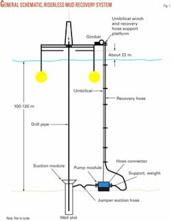
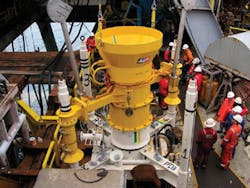
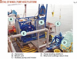
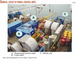
The riserless mud-recovery system is a very simple form of a dual-gradient drilling system.1 2 Fig. 1 shows a schematic of the system, together with photographs of the different components in Figs. 2, 3, and 4. The system consists of seven major components:
1. Suction module. The suction module (Fig. 2) functions as a collection funnel for mud returns from the well. It provides connections to the suction hose that permit mud and cuttings to be removed from the well. It houses the video cameras, lighting, and the mud-level control system. The suction module is deployed through the rig’s moon pool on the drillstring.
2. Pump and motor module. The pump module (Fig. 3) provides a support frame for the motor and pump. It is connected to the suction module by a flexible hose that is made up by the remotely operated vehicle. Power to the cameras, lamps, and level sensor on the suction module comes via a separate jumper umbilical line, also connected by the remotely operated vehicle.
The module includes a remotely controlled flow valve on the discharge side, a side outlet on discharge side for cement-return disposal, and an interface to the control system. The system has only a few, well-proven components. The Pleuger subsea motor is filled with a water-glycol mixture. Motor speed, and hence pump output, is controlled by a variable frequency drive. The Discflo pump has undergone extensive development with efficiency enhanced to 50%, high for this type of pump. A single pump drawing up to 300 kW is sufficient for water depths up to 200 m.
3. Umbilical and winch. The umbilical winch (Fig. 3) provides the power supply and control connection between the control container and the pump module. The umbilical winch is designed to enable launching and retrieval of the pump module over the side of the rig. Total length of the umbilical is optimized to the deployment depth for the pump module. The umbilical winch is built to Norsok Z-015 and DNV 2.7.1 standards.
4. Recovery hose system including handling platform. The recovery line provides for return of drilling fluid to the rig. It is made up in 15-m sections of 6-in. diameter heavy-duty hose joined by quick-connect couplings. The tensile strength of the hose is enhanced with a pair of load-bearing wires strung from integral lugs on each connector.
A special hose coupling and load-bearing wires enable efficient deployment and retrieval of the mud-recovery line. A remotely operated vehicle-friendly connector connects the recovery line to the pump module. The recovery-hose handling platform (Fig. 3) includes a safe handling system for deployment and retrieval of the recovery hose and a hang-off shoulder to take the weight of the recovery hose during operations. Hard piping connects the return hose landing platform manifold to the shale shaker header box.
5. Control containers and power supply. Two purpose-built containers (Fig. 4) were installed. One pressurized unit is a crew work area and operator workstation. The second pressurized unit contains the variable speed drive, transformer, filter, and control system to provide the interface between the rig and the system. A 3-kv transformer provides the high voltages to enable cable sizes to be optimized.
The container is the hub to which all control systems are interfaced. The control system monitors pump speed and pressures and also monitors and maintains a stable mud level in the wellhead suction module. The containers are fabricated to Norsok Z-015 and DNV 2.7.1 standards.
6. Control system. The control system controls the speed of the pump motor to keep the mud level below the top of the wellhead suction module, thus preventing escape of fluids to the sea. The control system is distributed between the control container and the subsea pump module. The system is controlled from a dedicated explosion-proof computer in the driller’s cabin.
7. Shutdown system. Emergency shutdown elements are part of the control system. The system was configured with two shutdown buttons, one on the drill floor, the other in the control container.
Project description
Modern project-management practice emphasizes the correct phasing of projects. Experience repeatedly demonstrates the benefits of a careful review of options and assessment of risks in the early stages of a project. Accordingly, the Sakhalin RMR project was broken into five steps with a formal “stage gate” review required before the project could progress to the next step.
• Appraise. The objective of this stage was to assess the feasibility of the concept. A review of available literature pointed to a candidate system. Discussions with the manufacturer suggested that a system could be developed and mobilized to commence operations in June 2006. A high-level risk assessment was carried out, a preliminary schedule prepared, and cost estimate developed.
Further work showed that the risks could be overcome and a system delivered within the required timeframe. This plan was networked with other business units and technical specialists who endorsed the viability of the project in June 2005. Funding was approved to carry out the necessary risk-reduction studies.
• Select. The purpose of this stage was to develop sufficient confidence in the concept to allow a commitment to be made to proceed with detailed engineering design and then, potentially, to full-scale system procurement and mobilization. Building on the risk assessment, planners visited the rig and carried out a series of preliminary risk reduction studies, specifically in relation to shallow gas and integrity of the recovery hose in the high currents.
During this phase, regular contact was maintained with another BP business unit employing the system as part of a template drilling operation in the Caspian Sea. An outline design of the system was developed with input of actual rig data, actual environmental data, and a rigorous input of operational procedures based on likely well designs. The output from this stage was a frozen design that demonstrated how the major risks were to be mitigated, how the system eliminated the need for pilot hole, and what effect it had on the chosen waste-handling method.
A detailed execution plan, budget, and commercial proposal were prepared and externally reviewed and approved in August 2005. At this stage the concept was de-risked to the point that funding for long-lead procurement items was approved.
• Define. The purpose of this stage was to develop a detailed design and specification of the system in order to proceed with manufacturing, certification, and installation. Given the schedule, it was necessary to identify and order long-lead items before the design freeze. The work to date had been carried out under a study contract, thus an agreement for the operational phase had to be developed.
Of critical importance early on was investigating matters relating to Russian certification and importation and developing the necessary action plan. Building on earlier work, the team completed detailed risk-reduction studies on the hose system and shallow gas behavior. Following the preliminary rig visit, Elvary Neftegaz held a series of meetings with the wellhead vendor and the remotely operated vehicle operator.
Once these initial studies were complete and preliminary plans devised, they were subject to a detailed operational hazard and operability review. After this review’s actions were identified, Elvary Neftegaz conducted a formal peer review of operational procedures involving shallow hazards specialists and senior technical authorities from drilling and completions. Formal approval to use the system in the 2006 drilling campaign was given in January 2006.
• Execute. The object of this phase was to deliver a working system to the rig in Busan, South Korea. It was necessary to procure the equipment, fabricate, and commission the system in Norway before disassembly and shipment to South Korea. Once in South Korea, in May 2006, the system was installed aboard the rig and commissioned. Detailed procedures for deployment and operation were developed and integrated with the main drilling operations plans for the wells. At this point, the RMR system was handed over to the well operations team.
• Operate. Use procedures for drilling operations, evaluate performance, capture lessons learned, and plan for next season.
• Project organization. Personnel in the UK coordinated the technical risk-reduction studies and contracting activities, but overall program administration and supervision was carried out in Sakhalin. Special consultancies in the UK and Norway performed the risk-reduction studies. The contractor in Bergen carried out the bulk of the engineering activity.
Interfaces between drilling contractor, wellsite supervision, wellsite service companies, and wellhead vendor were critically important. They were managed through a series of meetings in Singapore and South Korea. High-level peer reviews took place in Sakhalin and Houston.
• Key project risks. An initial high-level project risk assessment, carried out during the appraisal stage, formed the basis for a number of activities during the remainder of the project. The key risks and their mitigations were:
- Shallow gas: detailed engineering analysis.
- Integrity of umbilical in high current conditions: detailed engineering analysis.
- Use of the system in the Russian Federation: early start to permitting.
- Equipment lead-time: commitment of funds to enable procurement of critical items.
- Rig interface: early site visits, involvement of all parties, detailed hazard and operability review.
- New technology: extensive discussion and visits to other users.
Risk-reduction studies
Although BP had considerable experience using the system in the Caspian Sea, the metocean conditions off Sakhalin, with its strong current regime, posed significant problems. Elvary Neftegaz was concerned about system deployment, hose integrity, and the need to ensure the topsides equipment’s design rating would not be exceeded.
Elvary Neftegaz chose UK-based 2H Offshore Engineering Ltd. for the work based on its experience designing solutions for drilling and production riser systems. Environmental data for the study were derived from metocean data gathered in 2004, including current data recorded throughout the drilling operation with a seabed acoustic Doppler current profiler.
The resulting output endorsed selection of flexible riser material and validated design loadings for the umbilical winch and return line handling platform. Transocean Inc. the used these topside loadings to design and build the deck-strengthened foundations to mount the winch and handling platform, located starboard aft of the semisubmersible rig’s main deck.
Offshore systems team at BP’s technology center in the UK reviewed the study. There was some concern that internal abrasion of the riser hose might occur, given the large volumes of sand anticipated during drilling of top-hole sections. Calculations indicated that breaching of the hose liner was unlikely to occur before 1,000 hr of circulation at maximum pump rates. As the operation period was estimated to last some 2-5 days (100 hr maximum), this risk was considered negligible.
Concern was also expressed about the possibility of the hose kinking while in service. Kinking would not lead to damage of the hose, but simply a blockage of the recovery hose. Therefore, this was regarded as matter to be addressed through operational procedures as opposed to being an issue of fundamental technical integrity.
The possibility of gas entering the pump and recovery hose during a shallow gas blowout was evaluated even though the dual-gradient nature of the system, with the ability to control mud weight, makes it almost impossible for conditions to develop under which an influx can occur.
The Norwegian technology company, SINTEF, had already carried out some general scoping studies of this problem as part of the initial system development.5 SINTEF carried out a further, more detailed study using input data specifically related to the well design, hole sizes, mud properties, operational procedures, and anticipated geological conditions. The results of the analysis showed that:
- Use of the system in conjunction with a suitably weighted drilling fluid would greatly reduce the likelihood of a gas kick because of the “dual-gradient” behavior of the system.
- With a conventional influx volume of 3 cu m (20 bbl) as the detection threshold, kick detection is possible before gas reached the wellhead for all the kick scenarios and hole size combinations likely to be encountered.
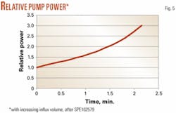
- Subsea pump power consumption is a sensitive method of detecting an influx. Fig. 5 illustrates the case of a 26-in. hole, in which it takes 2 min for the influx volume to reach 3 cu m, by which time the power demand has increased by a factor of 3. The control system is set to trip out following a 10% increase in power, in this case triggering a kick alarm within 15 sec.
- With kick development times ranging from 30 to 300 sec, ensuring no gas is taken into the pump and recovery hose demands a high degree of alertness and prompt action by the crew. The most rapid influx times were associated with pilot-hole configurations.
Further details of Elvary Neftegaz’s work with a riserless mud recovery system off Sakhalin will be published in the concluding part of this series.
References
- Smith, K.L., Gault, A.D., Witt, D.E., and Weddle, C.E., “Subsea Mudlift Drilling Joint Industry Project: Delivering Dual Gradient Drilling Technology to Industry,” SPE Annual Technical Conference and Exhibition, New Orleans, Sept. 30-Oct. 3, 2001, SPE 71357.
- Stave, R., Farestveit, R., Høyland, S., Rochmann, P.E., and Rolland, N.L., “Demonstration and Qualification of a Riserless Dual Gradient System,” OTC 17665, 2005 Offshore Technology Conference, Houston, May 2-5, 2005.
- Thorogood, J.L., Hogg, T.W., Kalshikov, A.G., “Exploration Drilling in the Russian Far East: Two Years of Experience and Learning Offshore Sakhalin Island,” SPE 99044, SPE/IADC Drilling Conference, Miami, Feb. 21-23, 2006.
- Murray, S.J., Williamson, M.D., Gilham, S., and Thorogood, J.L., “Well Design for Shallow Gas,” SPE/IADC 29343, SPE/IADC Drilling Conference, Amsterdam, Feb. 28-Mar. 2, 1995.
- Froyen, J., Rommetveit, R., Jaising, H., Stave, R., and Rolland, N.L., “Riserless Mud Recovery (RMR) System Evaluation for Top Hole Drillling with Shallow Gas,” SPE 102578, 2006 SPE Russian Oil and Gas Technical Conference and Exhibition, Moscow, Oct. 3-6, 2006.
The authors
John D. Brown (john.brown @uk.bp.com) is senior drilling projects engineer with CJSC Elvary Neftegaz, Yuzhno-Sakhalinsk, Russia. He has worked as technology team leader and drilling manager for BP. Brown has an HND (Higher National Diploma) from the Stockton and Billingham Technical College and is a member of SPE.
Viktor V. Urvant ([email protected]) is the permitting manager at CJSC Elvary Neftegas, Yuzhno-Sakhalinsk. He previously worked on logistics for Schlumberger/Dowell in the Shell-operated Sakhalin 2 project. Urvant holds a Diploma (1985) from Sakhalin State University and attended drilling courses in Aberdeen.
John L. Thorogood ([email protected]) is chief drilling engineer at CJSC Elvary Neftegaz, Yuzhno-Sakhalinsk. He has worked for BP for 34 years in many parts of the world. Thorogood has a BA and a PhD from the University of Cambridge and is a member of SPE and the Institute of Mechanical Engineers.
Nils Lennart Rolland (nlr@ agr.no) is the engineering manager at AGR Subsea AS, Bergen, Norway. He has more than 35 years experience with systems engineering for well drilling, completion, production, and subsea intervention technologies, working in Norway, UK, US, and Indonesia. Rolland recently managed the Demo 2000 RMR project, served as base manager for Cameron Norge AS in Bergen, and as base manager for FMC Corp. in Jakarta. He has also worked for Statoil, Norsk Hydro, Stolt Offshore, Aker Group, NeoDrill AS, DSND Subsea AS, Betex AS, AS Fjell Industries, Sigma Enterprises, among others. Rolland has a degree (1970) in mechanical and industrial engineering from Bergen Technical College and is a member of SPE and NPF.
