SPECIAL REPORT: Statoil to begin Snøhvit LNG operations by yearend 2007
Statoil’s Snøhvit LNG plant comes on stream later this year.
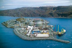
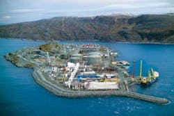
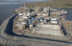
Commissioning of the plant, built on Melkøya island outside Hammerfest in northern Norway (Fig. 1), got under way late last year, and in February these activities were progressing according to schedule. LNG shipments are to begin in the fourth quarter, with contractual deliveries starting on Dec. 1, 2007.
Snøhvit LNG will be produced with the mixed-fluid cascade (MFC) liquefaction process developed by Statoil and partner Linde AG. The project has paved the way for Statoil to become a gas supplier to the US market.
Start-up at Snøhvit will also be significant for the LNG world, marking the first baseload LNG production in Europe and, with a location at 71ºN, within the Arctic Circle, it will be the world’s most northerly baseload LNG plant.
Because of limited infrastructure in northern Norway and difficulties of constructing a plant in winter, a prefabrication policy was adopted, whereby most of the modules were built elsewhere in Europe.
On the supply side, the project is also noteworthy. Snøhvit and the two neighboring fields that will supply gas, Askeladd and Albatross, are the first hydrocarbon reserves to be developed in the Norwegian part of the Barents Sea and the most northerly hydrocarbon development to date.
The fields are tied back directly to shore over 143 km, the longest offshore step-out involving multiphase transport to date. It was the first offshore development to be approved by Norwegian authorities that does not involve surface installations.
Because of the environmental sensitivity of the region, the project has been subject to strict environmental requirements. One consequence is that carbon dioxide will be extracted from the gas and returned to the field to be stored in a subsurface formation, the first time this has been done from an onshore plant. Offshore production is in the form of a closed-loop system, with no discharges to the sea or air.
Gas production will be 6.9 billion cu m/year (bcmy), from which 4.3 million tonnes/year (tpy) of LNG will be produced. Reserves on which the project is based-more than 190 billion cu m of gas and 20 million cu m of condensate-are sufficient for about 30 years’ LNG production. Statoil is optimistic, however, that it can firm up sufficient new reserves to justify installing a second LNG train.
A significant part of the world’s undiscovered hydrocarbon reserves is believed to lie in Arctic waters, and a substantial portion of these is believed to be gas. The experience gained at Snøhvit, both from the offshore development and the LNG project, including the MFC technology and the prefabrication philosophy, will prove valuable for future such projects in the Arctic and other remote locations.
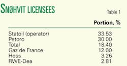
The company’s partners in the project are Gaz de France, Hess, Petoro, RWE-Dea, and Total (Table 1).
Developing LNG technology
When Snøhvit, Askeladd, and Albatross fields were discovered in the early 1980s, Statoil faced the double challenge of how to develop them and how to market the gas, given the remote location. The only solution to the marketing challenge was LNG.
In Statoil’s view, however, LNG technology development had become static; there were too few players in the market and too little competition. Undertaking its own technology development would help inject more competition into the technology market.
Under a framework agreement with the Norwegian Institute of Technology (NTH), Statoil undertook fundamental studies of liquefaction processes with a focus on heat-exchanger calculations and improving the accuracy of thermodynamic information. This intense research effort yielded the knowledge and tools to model and simulate the entire process.
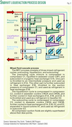
Statoil also began cooperating closely with Linde, a German company specializing in low-temperature industrial processes with a special expertise in heat-exchanger technology. In 1996 the two companies established an LNG technology alliance under which the MFC process was developed (Fig. 2).
MFC is a hybrid process, combining features of the classic cascade cycle with the mixed-refrigerant cycle. It consists of three cooling stages, each with its own composition of refrigerants:
- Precooling to -50° C.
- Liquefaction to -80° C. at 60 bar.
- Subcooling to -155° C., also at 60 bar.
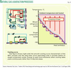
Careful tailoring of the composition and relative volumes of the refrigerants to each cooling stage makes it possible to achieve an exceptionally close match to the idealized cooling curve using as little power as possible. Cooling takes place smoothly and economically, rather than step-wise, as is typical of the classical cascade process (Fig. 3).
Benchmarking has shown that the MFC process is competitive in terms of energy efficiency with other liquefaction processes.
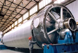
Drawing on the much-improved knowledge of heat-exchanger process, Linde designed a state-of-the-art spiral-wound heat exchanger (SWHE; Fig. 4). A prototype underwent a comprehensive test program at PetroSA’s gas-to-liquids plant in Mossel Bay, South Africa, in 1998-2000, with encouraging results.
Snøhvit plant design
MFC was one of three liquefaction processes evaluated by the Snøhvit project and in 2000 was selected on the basis of a competitive bid. Production capacity was set at 4.3 million tpy of LNG from a single train, a level chosen as offering the best combination of economy of scale with moderate technology, plant complexity, and other relevant factors.
A priority in designing the Snøhvit plant was to realize benefits inherent in the MFC process and especially its high energy efficiency. The need for compactness, given space limitations on Melkøya Island, near the town of Hammerfest, and the requirement for low emissions, were also important.
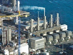
Power generation is based on five LM6000 (Fig. 5) gas turbines. These are aeroderivative models with very efficient fuel consumption and low emissions. They are also well known to Statoil, which uses them on offshore platforms and at onshore gas processing plants.
Each turbine supplies power to an internal grid at a rated capacity of 46 Mw. The regional electricity grid provides back-up power at 50 Mw. A hot-oil waste-heat-recovery system on each turbine provides process heat.
Another important feature is that the compressors are run by electric variable-speed motors, the first use of all-electric drive in an LNG plant. This decision, which was driven by the need to minimize greenhouse-gas emissions, involves a higher investment than the conventional direct mechanical drive, but also has the economic benefit of making available an additional 10 days/year on stream. Plant availability is thereby increased to 340 days/year.
The configuration of the energy-generation facilities is the basis for highly efficient energy use-electricity efficiency of 41% and an overall thermal efficiency of 71%. Moreover, less than 6% of overall gas production is required as fuel for the turbines, a good indicator of the overall energy efficiency of the plant. When Snøhvit’s energy consumption was benchmarked on equal terms with an LNG industry flagship, Snøhvit came out significantly better.
A major natural advantage also derives from the project’s location within the Arctic Circle with respect to the seawater used as cooling medium. Drawn from a depth of 80 m, the water has an ambient temperature of only 5° C., much lower than in hot coastal environments. As a rule of thumb, each 1% reduction in the temperature of the cooling water leads to a 1% gain in efficiency of the process.
The power requirement of the three-cycle compressors for LNG production of 4.3 million tpy is 127 000 kw, which in combination with the cooling-water conditions, gives the process a specific refrigeration power of 234 kw-hr/tonne of LNG produced. In Statoil’s view, this makes Snøhvit the most energy efficient LNG plant yet designed.
One of the solutions adopted to achieve compactness of design was the use of cold boxes to house the heat exchangers. Inside the boxes, void space around the cryogenic equipment and piping is filled with perlite insulation. The cold boxes are installed in the cold-box assembly with liquefaction and subcooling boxes at the bottom and the precooling box on top of them.
Liquefaction and subcooling take place in the SWHEs and precooling in a plate-fin heat exchanger. Both the SWHE units have a diameter of almost 5 m. In the subcooling unit, which stands 27 m high, each aluminum tube is about 100 m long, with an external diameter of 10-12 mm and a 1-mm wall thickness. The aluminum tubes are a combined 500 km long, giving a very extensive total cooling area. The liquefaction heat exchanger is somewhat smaller, standing 22 m high.
Processing flow
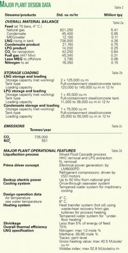
The well stream from the offshore fields arrives at the Hammerfest LNG plant with a pressure of 70-90 bar and a temperature of between -5° C. and 4° C. Figs. 2 and 3 display flow diagram and operational information.
The stream first passes through the slug catcher, in which liquid slugs are buffered or dispersed and an initial separation of the three phases-natural gas, condensate, and a water/monoethylene glycol (MEG) mixture-takes place. Because of space limitations on site, the slug catcher is designed to resemble a bent finger (Fig. 6).
The condensate flows to the condensate separator and the water-MEG mixture to the MEG-regeneration unit where water is removed and MEG regenerated and stored in one of four tanks ready to be piped back to the field.
From the slug catcher, natural gas passes to the inlet facilities. On the way it is heated to prevent formation of hydrates and the pressure is stabilized at around 70 bar. The inlet facilities strip out any remaining liquids. Some gas is then removed from the flow for use as fuel gas.
The next phase-pretreatment-removes in successive stages CO2, water, and mercury from the gas. CO2 is removed by flowing the gas through an amine compound, in the course of which CO2 binds to the amine. CO2 is then separated from the amine by heating the mixture. It is then dewatered and compressed, in order to liquefy it, after which it is ready to be piped back to the Snøhvit field for injection into the subsurface.
The Gas then goes through the first of the three stages of refrigeration in which it is precooled to -50° C. It then passes into a fractionation column, where heavier components such as propane and butane are removed in order to adjust the calorific value to sales specification. The heavier components are extracted and piped to the LPG fractionation system.
Precooled lighter gases, primarily methane and ethane, return to the cold-box assembly where they pass through the liquefaction and subcooling processes. Following subcooling, the temperature of the liquid gas is reduced to -163° C. from -155° C. in two stages:
- Through a process of internal heat exchange in which LNG is used as heating medium for nitrogen removal.
- By passage through an expansion turbine, which reduces the gas’s pressure. The gas is then piped to one of the two storage tanks; Table 2 shows major plant operational data.
Plant construction
In March 2002 the project received the official go-ahead, when the plan for development and operation (PDO) was approved by the Storting, the Norwegian parliament. The greenfield site on Melkøya Island is about 5 km from the town of Hammerfest on Norway’s northern coast.
Detailed design of the plant was contracted to Linde, with assistance from Aker Kvaerner. Linde was also responsible for supplying the heat exchangers. Installation and hook-up of the plant was awarded to Aker Stord, supply of electrical and control systems to ABB, and an order for the refrigerating compressors and five gen-sets to Nuovo Pignone.
The five LM6000 gas turbines were ordered from General Electric and the electric motors from Siemens. An engineering, procurement, and construction contract was awarded to Belgian company Tractebel for storage and loading facilities, including the four storage tanks (two for LNG, one for LPG and one for condensate).
In view of the Arctic location and limited regional infrastructure and resources, a construction policy of maximum prefabrication was adopted. In particular it was decided that process equipment and power-generation facilities would be assembled on a barge that would be installed in a specially prepared dry dock at Melkøya.
All major modules were built at sites on mainland Europe, including the process plant at the Dragados yard in Spain. Heerema in Holland and Fabricom in Belgium were responsible for several of the process and utility modules. Heerema also built the slug-catcher and MEG regeneration units and Fabricom the pipe racks and electricity substations.
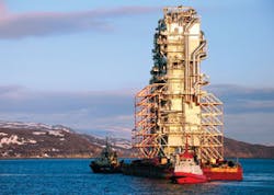
Most of the modules were shipped to Melkøya during 2005. Key deliveries were a shipment containing two MEG reclamation units and three electricity substations that arrived in February 2005, the cold-box assembly that arrived the following May (Fig. 7), and the process barge, which arrived on the Dockwise heavy-lift vessel Blue Marlin after an 11-day journey in July 2005.
The total weight of the barge, which measures 154 x 54 m and supports equipment structures up to 50 m high, is 35,000 tonnes (topsides 25,000 tonnes, base 10,000 tonnes). On arrival at Melkøya, it was floated off the heavy-lift vessel and, after a couple of days’ wait for suitable weather, winched into the dock. Water was drained and the barge concreted into place.
The cold-box assembly, which stands 60 m tall and weighs 2,625 tonnes, is located alongside the barge.
Cost, schedule overruns
LNG deliveries had originally been scheduled to start in October 2006, but in September 2005 Statoil announced that the schedule was to be extended to December 2007 and the budget increased. The budget, which covers both LNG plant and offshore development, including future drilling phases, had already risen to more than the 40 billion kroner (about $6.4 billion in 2005) estimated at the time of project approval, was further increased to 58.3 billion kroner. The project team was strengthened and the project brought under responsibility of the technology and projects business area.
The immaturity of the project at the time of sanction led to changes in both the engineering and the project execution. As a result, the project experienced significant increases in work scope for several activities, especially electrical installations, electrical control systems, insulation, and heat tracing.
Significant weight increases had also taken place for some of the modules. In particular the weight of the plant to be installed on the process barge had become too great, so that it had already been decided to take off the cold-box assembly.
Another consequence of these developments was that it became impossible to perform module testing at the yards without incurring further serious delays. Instead it was decided to transfer the outstanding work to Melkøya, where the work-scope of Aker Kvaerner and its subcontractors was expanded to cover the additional requirements.
Commissioning program
Work is now for the most part up to the revised schedule. By early this year, almost all installation was complete, with a modest volume of insulation and heat tracing still to be finished.
In mid 2006, the first system, the air-separation unit, was commissioned. In the remaining months of 2006, the other utility systems were commissioned and brought into operation.
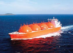
Important milestones were reached in December 2006, first with the change in the status of the Melkøya plant from construction site to gas processing facility and, just before yearend, with import of gas for commissioning. This came as a 140,000-cu m cargo of LNG delivered by Arctic Princess (Fig. 8), one of the carriers built to serve the project.
The cargo was used to cool the storage tanks. In mid February, it was regasified for use as fuel gas to bring the power-generation plant into operation, generating about 100 Mw. Next follows commissioning of the process plant, starting with the cooling compressors.
The slug catcher, MEG-regeneration system, and CO2 extraction system will be commissioned and ready for operation ahead of first gas on May 1. In early July, gas is to be fed into the process plant, opening the way to the start-up of this plant in the following months. The first LNG shipments are to take place during fourth quarter, ahead of start of contractual deliveries on Dec. 1.
Operations
The knowledge acquired in developing and qualifying the MFC process and SWHE will also be applied to optimize operations of the Snøhvit plant. For the first time in an LNG plant, a rigorous model of the main SWHE will be used, incorporated in a comprehensive dynamic simulator.
Special scientific instruments will also be used to check performance of the heat exchangers and validate tools used in their original design. Instrumentation data will be combined with simulations to optimize plant performance.
Another approach to optimization is based on detailed SWHE models that are used as modules in flow-sheet programs, thus enabling parameters such as flow rates, temperatures, pressures, and refrigerant composition to be fine-tuned in order to maximize LNG production.
Control room operators will also use a virtual model of the Snøhvit value chain, from reservoir to LNG process, in order to visualize operations and facilitate decision-making when deviations from normal operational patterns occur. The technology will be the first such visualization tool in the world.
About 180 personnel will be involved in running operations, including a small number responsible for controlling offshore facilities. There is an operations organization of around 100, including control room staff and various sets of crews for carrying out either planned or unscheduled maintenance. There is also an operations support staff of around 70, including engineers, laboratory staff and the harbor crew, project personnel, management, and administration.
Snøhvit LNG fleet
Statoil, Petoro, Hess, and RWE-Dea have sold their share of production, about 70%, to Statoil North America and the Spanish company Iberdrola. Under these agreements, 1.8 million tpy will be delivered to the Cove Point, Md., terminal on the US East Coast, which is partly owned by Statoil, and 1.2 million tpy to Bilbao in northern Spain. Gaz de France and Total will lift their 1.3-million tpy shares separately.
LNG shipments numbering around 70 LNG/year will be made. Four 140,000-cu m newbuild LNG carriers, two by Mitsubishi and one each by Kawasaki and Mitsui, will serve the Snøhvit trade. Three (Arctic Discoverer, Arctic Voyager, and Arctic Princess) will serve the Statoil North America and Iberdrola contracts; Statoil is a part-owner of all three. The fourth, Arctic Lady, has been jointly chartered by Gaz de France and Total.
Future
The next step in the Snøhvit story will be to add another processing train. First, additional gas quantities must be proven up, either in the Snøhvit field or elsewhere in the region. Layout and other technical studies have already begun, based on the experience from Train 1, and it is important that some of the personnel from the current project join the project for a second train when they are demobilized.
Meanwhile the Statoil/Linde alliance, which has been extended to 2008, has been working to develop the LNG technology further. One main avenue has been application of the MFC process to high baseload projects, taking advantage of the flexibility provided by use of different refrigerant mixes for each cycle. Engineering studies have shown that production of 9-12 million tpy from a single train is achievable.
Work has also been carried out to apply the technology to floating LNG production. For this application, Aker Kvaerner has joined the alliance, bringing its expertise in floating technology and project execution. Linde has qualified the SWHE for use in a floating environment. The possible use of CO2 as a refrigerant has been studied.
The Linde SWHE has proven attractive to other LNG projects, and units have been sold to a number of new projects, including Shell’s Sakhalin II.
The author
Odd Arild Mosbergvik ([email protected]) is senior vice-president, Snøhvit development for Statoil ASA, Stavanger. Since 1979 he has held various project planning and management posts at Statoil, becoming project director in 1992. Since then he has directed, among other projects, the Åsgard field development (1996-2000), Borealis’ Borouge petrochemical development (2001-02) and extension project (2003-05), and the South Pars Phases 6, 7, and 8 field development in Iran (2002-03). He holds an MSc (1976) in physics from the Norwegian Institute of Technology. He is a member of the Norwegian Society of Chartered Engineers. (photo by Knut Helge Robberstad, Statoil)
