Standards Activity - 1: Ormen Lange long free spans prompt update
A major testing campaign and research program conducted around the Ormen Lange project off Norway sought to develop subsea long free-span design procedures in compliance with Det Norske Veritas standard DNV-RP-F105 design philosophy in an effort to minimize free-span intervention costs.
This first of two articles examines the shortfalls of existing standards as applied to Ormen Lange, as well as the testing and analysis that ultimately not only helped determine the route of the Ormen Lange export pipeline but also led to an update of DNV free-span standards.
The second article will focus on particular design parameters for free-spanning high temperature-high pressure pipelines such as Ormen Lange and illuminate a case study of Ormen Lange that can be applied to other HTHP pipelines.
Categories
Free-span assessment of subsea pipelines requires detailed knowledge in disciplines such as vortex-induced vibrations (VIV) and direct wave load models, environmental modeling, fatigue calculations, structural response analysis, and assorted geotechnical fields.
The relevant failure modes for free spans are fatigue and local buckling. Accumulated damage from stress cycles caused by VIV, with contributions from direct wave loads in shallow waters, may cause fatigue. Overstress (local buckling) due to static bending (weight and current), VIV and wave loads, pressure effects, and axial force also need to be considered. Trawl gear interference analysis can provide limiting conditions in trawling areas.
This article will restrict its focus to VIV aspects of very long free-spanning pipelines.
The following categories can help classify and analyze free-span vibrations:
• Isolated single span, single-mode response.
• Isolated single span, multimode response.
• Interacting multispans, single-mode response.
• Interacting multispans, multi-mode response.
Design code DNV-RP-F105 effectively covers both single and multiple spans vibrating predominantly in a single mode. The combination of long spans and high currents, however, may not only activate the fundamental eigen modes but also higher modes.
The design codes do not prohibit such a multimodal response. Nor, however, do they provide detailed guidance about the fatigue damage from multimode vibrations.
Ormen Lange free spans
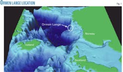
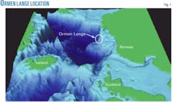
The Ormen Lange gas field is 120 km west of Kristiansund, off Norway (Fig. 1). It lies within a gigantic prehistoric slide, under water 800 to 1,100 m deep. Development includes subsea installations, with the gas transported to shore by two 30-in. multiphase pipelines. The prehistoric slide created a very uneven seabed, including steep slopes and obstacles up to 50 m tall.
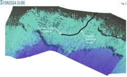
Fig. 2 presents a 3D view of the Storegga slide, including the development area for the wells and templates at 850 m deep. Fig. 2 also shows the pipeline route from the subsea installations, out of the slide area, and towards the onshore terminal.
Fig. 3 shows a local view of the uneven seabed in the development area.
This article presents an overview of the activities performed in the project to minimize the span-intervention costs by advanced routing and development of a new design approach to document the integrity of long free spans.
It also briefly discusses recent updates of DNV-RP-F105 regarding design methodology, response models, and acceptance criteria.
Free-span design
Current design practice for free-spanning pipelines allows free spans if their integrity with respect to potential failure modes is checked and found acceptable.1
Ormen Lange’s uneven seabed will cause a high number of spans, some very long and with a large pipe-seabed gap.
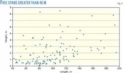
Fig. 4 plots all spans longer than 40 m for an early pipeline route. The steep slopes in some areas will also cause challenges in seabed preparation and span intervention. Additionally, the 100-year extreme value for the near-bottom current is greater than 1.1 m/sec. Such currents restrict the allowable span lengths due to VIV and associated fatigue and are motivating efforts to extend the existing practice for allowable span lengths while still not compromising the overall safety objective.
Very long spans exposed to high current velocities for long duration require that the multimode behavior for inline, cross-flow (CF), and CF-induced inline be taken into account. This accounting calls for advances in the design guidelines to provide explicit methodologies for assessing multispan pipelines vibrating in multiple modes.
-span design, in addition to ensuring the structural integrity of the pipelines, will focus on minimizing the seabed preparation and span intervention costs. For Ormen Lange this has meant:
• Advanced routing activities.
• A current-measurement campaign and current-modeling activities.
• A laboratory VIV test campaign for realistic multispan scenarios.
• Updated, project-specific design guidelines based on test results.
• Use of reliability analysis for the free spans.
Advanced routing
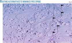
The conceptual study and detailed design phase of Ormen Lange evaluated several pipeline routes, conducting detailed surveys of each of them with autonomous underwater vehicles. The detailed mapping of possible routes made it possible to optimize the pipeline route. This optimization also made it possible to avoid several of the longest free spans encountered in early phases of the planning (Fig. 5).
VIV tests
The Norwegian Marine Technology Research Institute (Marintek) performed a test program to gain experience and data regarding long free-span response.2 3 Analysis of the test results concluded with a calculation procedure on how the interaction between CF and inline VIV response could be treated in long free spans.4 5 On this basis, a project-specific guideline for long free spans was developed, built on the design methodology of DNV-RP-F105.
The set-up of the test rig used a removable clamp support, enabling changes in span length. The model was 1:17 scale and applied Froude scaling law. The bending stiffness of the test pipe reflected the bending stiffness of the Ormen Lange pipe, while the tension in the pipeline was adjusted in the tests by a pre-tensioning device. The L-D span length ratio varied between 145 and 350.
Towing the test rig through water in a ship model tank allowed the vortex-induced vibrations to be measured for different flow velocities or reduced velocities, as used in the response models. During towing, strain gauges measured the strains at different locations and video recorded the vertical and horizontal displacements.
The multimode behavior of the long free spans appears vividly in the model tests conducted at Marintek. Fig. 6 shows the multimode behavior of the free span with an L-D ratio of 215.
Displacement measurements during the time window of 454 and 464 seconds provided the basis for Fig. 6. The first two CF modes and the first three IL modes are active. Similar multimode behavior has been observed in several test cases.
A design procedure for multiple spans’ VIV used the identified effects, which were implemented into the Ormen Lange project guideline.6
Standards update
In principle, there is no limitation to the span length DNV-RP-F105 covers. The basic CF VIV response, however, is based on single-mode response and therefore focuses on short to moderately long spans. Cases of very long spans exposed to high current velocities for long durations require that the multimode behavior for IL, CF, and CF-induced IL be taken into account.
DNV-RP-F105 applies so-called response models to predict the vibration amplitudes caused by vortex shedding. These response models are empirical relations between the reduced velocity and the nondimensional response amplitude. The reduced velocity is the most important hydrodynamic parameter in VIV calculations as it links the natural frequency of the span to the shedding frequency given by Strouhal expression (VR = U/ƒoOD, where U is the flow velocity, ƒo the natural frequency of the span, and OD the outer diameter of the pipe). Test data and a few hydrodynamic and structural parameters provide the basis for the response models.
Strouhal’s number, pipe OD, and flow velocity govern the vortex-shedding frequency caused by a flow normal to a free span. As the flow velocity, and thereby the shedding frequency, reach one of the natural frequencies of the span, the span starts to vibrate and the vortex shedding along the span gets correlated by the vibration of the span. In this way, the vortex shedding frequency and the VIV become locked-in with the natural frequencies of the span over a certain range of flow velocities.
The response frequency may differ from the calm water natural frequency.4 5 7 This is related to a change in added mass. As the vibration amplitude of the span increases, the motion of the pipe will change the relative flow velocity and will therefore influence and eventually break down the vortex shedding at limit. In this way, the VIV assumes the characteristics of a displacement-controlled load with limiting A-D values.
The response models given in DNV-RP-F105 were studied for applicability to long free spans. The results from the model VIV tests conducted at Marintek identified the response models that needed to be modified. The inline response model given in DNV-RP-F105 captured the inline response behavior of long free spans, even for higher modes, and was therefore considered adequate.
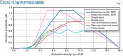
The cross-flow response model required some modifications in order to capture the observed VIV response behavior. Two CF response model options were proposed and tested for their suitability.
Fatigue analysis also performed on the stress series measured in the model tests verified and validated the presented computational procedure. DNV assessed uncertainty in the model test-based fatigue estimates and conducted sensitivity studies identifying reasons for any deviations and potential problem areas in long free-spanning pipelines.
Summarizing the main findings of the VIV tests and developing a project specific design guideline yielded:
• The identification and examination of response models for cross-flow (Fig. 7).
• Determination that DNV-RP-F105 in-line response model was sufficient and applicable.
• The inclusion of added-mass effect in calculating the response cross-flow frequency.
• Reasonable agreement in the ratio between fatigue estimates based on the computational method and fatigue estimates based on model tests, with quantifiably small deviations.8
Reliability analysis
A reliability approach allows dedicated uncertainty modeling, including statistics for natural variability and explicitly accounting for model uncertainties. Given this, a design procedure with calibrated fatigue safety factors can ensure design with acceptable failure probability. The study of Ormen Lange regarding free-span fatigue used this approach, allowing a more accurate prediction of maximum allowable span lengths than is possible with a design code whose safety factors are developed for a broader scope of design conditions. The reliability analysis also gives valuable sensitivity measures that support design modifications and cost optimization.
Sensitivity studies performed included:
• Acceptance level (annual probability, system effects).
• Pipe (wall thickness).
• Effective axial force.
• Span (length, gap).
• Soil (firm, stiff, soft).
• Current (distribution, depth, direction).
• Response analysis (response curve, eigen frequency, damping, concrete stiffness, static deflection).
• Cyclical stress vs. cycles to failure (air, corrosion, curve).
• Damage (allowable, stress amplitude).
Additional studies included the effect of using strakes and monitoring of VIV.
These studies, using probabilistic analysis, showed:9
• Fatigue for most free-span scenarios is governed by first and second-mode IL VIV.
• DNV-RP-F105 provides conservative results for operational conditions.
• Governing uncertainties are related to:
-SN curve
-Eigen frequency
-Stress amplitude.
Acknowledgment
The Ormen Lange license group funded these studies. Norsk Hydro AS and its license partners BP PLC, ExxonMobil Corp., Petoro AS, Royal Dutch Shell PLC, and Statoil ASA granted permission to publish these results. The model tests were conducted at Marintek. Reinertsen Engineering AS analyzed the model test results and performed modal analysis. ✦
References
1. “Recommended Practice: Free-spanning Pipelines,” DNV-RP-F105, March 2002.
2. “Ormen Lange 3D model tests,” Marintek report 512326.00.01, March 2001.
3. “Ormen Lange 3D Phase II model tests,” Marintek report 512352, July 2002.
4. Nielsen, F.G., “A suggested procedure for estimating vortex-induced vibrations for long free-spanning pipelines,” Norsk Hydro Report, 2002.
5. Nielsen, F.G., Kvarme, S.O., and Søreide, T., “VIV Response of Long Free-spanning Pipelines,” 21st International Conference on Offshore Mechanics and Artic Engineering, Oslo, June 23-28, 2002.
6. “Ormen Lange - Design Guideline for VIV of Long Free-spanning Pipelines,” DNV Report 2002-0967, Rev. 2, Jan. 2003.
7. Larsen, C.M., Vikestad, K., Yttervik, R., and Passano, E., “Empirical model for analysis of vortex-induced vibrations-Theoretical background and case studies,” 20th International Conference on Offshore Mechanics and Arctic Engineering, Rio de Janeiro, June 3-8, 2001.
8. Mørk, K.J., Fyrileiv, O., Chezhian, M., Nielsen, F.G., and Søreide, T., “Assessment of VIV-induced Fatigue in Long Free-spanning Pipelines,” 22nd International Conference on Offshore Mechanics and Artic Engineering, Cancún, Mexico, June 8-13, 2003.
9. Hagen, Ø., Mørk, K.J., Nielsen, F.G., and Søreide, T., “Evaluation of Free-spanning Design in a Risk Based Perspective,” 22nd International Conference on Offshore Mechanics and Artic Engineering, Cancún, Mexico, June 8-13, 2003.
Based on presentation to Rio Pipeline 2005 Conference, Rio de Janeiro, Oct. 17-19, 2005.
The authors
Olav Fyrileiv is a principal engineer in the pipeline section of DNV, Høvik (Oslo). He holds a PhD in nonlinear finite element analysis from the Norwegian University of Science and Technology, Trondheim.
Kim Mørk is current head of section for risers, mooring and umbilicals in DNV, Høvik. He holds a PhD in stochastic mechanics and is the author of more than 70 papers regarding riser and pipeline technology, VIV, and probabilistic analysis.
Muthu Chezhian ([email protected]) is senior engineer at DNV, Høvik (Oslo). He holds a PhD (2003) from NTNU, Trondheim. He is a member of the API RP-2RD task group.
Finn Gunnar Nielsen is current chief engineer at Norsk Hydro Research Centre, Bergen, and adjunct professor in marine technology at the Norwegian University of Science and Technology, Trondheim. He holds a Dr. Ing. degree in marine hydrodynamics (1980).
