Low-pressure gas well deliquification requires different approaches
Deliquification of a low-pressure gas well requires a different approach, tools, and staffing than artificially lifting an oil well.
There is no “silver bullet” that will solve all deliquification problems in all fields or even in all wells within a field. The energy available to lift reservoir fluids at low pressures requires application of considerable subtlety to the process and demands that the well operator understand that a few pounds of pressure drop could easily be the difference between success and failure.
Deliquification
Wells originally drilled and equipped with a 500-psig expected abandonment pressure can still produce economic quantities of gas at current US gas prices. Operators now frequently ask the question “What do I have to do differently to change abandonment assumptions by 300-400 psig?”
The primary difference between high-pressure operations and low-pressure operations is deliquification. With high bottomhole pressure, gas has considerable density and consequently good ability to move liquid up the wellbore without assistance. As pressures decrease, this ability lessens and the well often needs some form of mechanical deliquification equipment.
Deliquification is a different concept from artificial lift. Artificial lift applies an external energy to lift a commercial product from reservoir depths to the surface, whereas deliquification applies energy to remove an interfering liquid to enhance gas production.
While the industry originally developed many deliquification tools for artificial lift, the application of these tools is significantly different in gas wells.
Most obviously, artificial lift requires getting the product to the surface, while deliquification only requires getting it out of the way. Evaporation is an effective deliquification technique but would be unacceptable for artificial lift.
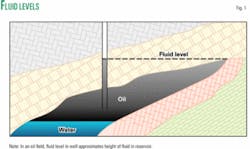
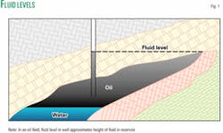
Another significant difference is net positive suction-head (NPSH) requirements. An oil well can have a liquid level in the wellbore as high as the hydraulic gradient within the formation. For a well located downdip from the reservoir’s hydraulic surface, having several hundred feet of oil in the casing above the pump has no effect on flow from the reservoir while it does provide the NPSH to fill the pump (Fig. 1).
A low-pressure gas well does not have a measurable hydraulic gradient across the formation so that any liquid above a pump-intake is applying “unnecessary” backpressure on the formation. Operators of mechanical pumps need to understand both the required NPSH (NPSH-r) and the available NPSH (NPSH-a).
NPSH-r is the pressure at the pump inlet that will prevent cavitation in a rotating or jet pump or ensure adequate fill of a stroking pump.
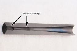
Cavitation is the formation and subsequent collapse of vapor bubbles in a flow stream. This means that when the pressure in the flow becomes too low, the liquid can boil and develop steam pockets. As the liquid moves through the pump, pressure will increase to the point where the steam must condense. The condensation creates a void in the liquid that is filled by high-velocity liquid moving to fill the void. The momentum of this rushing liquid can tear metal from the control surfaces of the pump (Fig. 2).
A stroking pump with inadequate NPSH will see partial filling, such as the standing valve not having enough differential pressure across it to open, and the pump can gas lock.
NPSH-a is simply the pressure at the pump inlet that is available from either hydrostatic or pressure sources.
For a pump to operate on its pump curve, NPSH-a must be greater than the NPSH-r.
Many operators will extend the wellbore casing a considerable distance below the formation to create a rat hole. Placing a pump in the rat hole is a common method to try to increase the NPSH-a without imposing an artificial backpressure on the well. This sometimes works well. At other times, the liquid volume in the rat hole is so small that, while it may provide adequate pressure (which is only a function of liquid properties and height, not volume), it does not provide enough reserve.
When liquid inflow stops, such as when one shuts in the well with the pump running, a pump can pull the fluid level to below the NPSH-r in a few seconds, damaging a pump.
The well with a rat hole may require more attention and instrumentation instead of less as commonly believed. In the author’s experience, a rat hole often improves steady-state pumping conditions while significantly increasing the potential for damage in an upset condition.
Derived techniques
The deliquification techniques that have evolved from artificial lift all require either subtle or major changes for gas well operations.
For example, if a reciprocating pump requires 100 ft of NPSH, then one has to accept 44 psi of extra backpressure on the formation, an important factor in calculating abandonment pressure.
For any artificial-lift pump to work in deliquification, one has to carefully balance NPSH needs, liquid inflow, and pump capacity.
For example, a well produces 5 bw/d and has a 11⁄2-in. rod pump inside 23⁄8-in. tubing in 51⁄2-in. casing. If the pump runs at 4 spm with a 40-in. stroke, the pump capacity is about 44 b/d. If the NPSH is 100 ft (1.8 bbl) and the pump runs continuously, the pump will have lifted all of the daily inflow in about 4 hr, leaving it moving up and down without pumping for the remainder of the day.
In reality, this configuration will tend to pump liquid for 5-10 min followed by 2-3 hr of gas lock throughout the day. Sometimes the best option is to reduce the size of everything.
An operator could install a 1-in. pump running 2 spm with a stroke length of 25-in. to reduce the capacity to 6 b/d, and then the well would probably only gas lock 2 or 3 times/day instead of 12-14, but the results are the same. It is very difficult to match pump performance to inflow.
The following sections describe the derived deliquification techniques including pump-off control, stroking pumps, progressing cavity pumps (PCPs), electric submersible pumps (ESPs), gas lift, jet pumps, and surfactant injection,
Pump-off control
Operators have a wide range of artificial-lift pump-off control schemes that range from a simple stop-clock to elaborate algorithms. All these schemes help protect against the NPSH-a approaching the NPSH-r. But for deliquification, none of the schemes works well.
Typically in a compressible-flow regime, surface indication to stop pumping arrives too late.
In the previous example, the pump can move 44 b/d and the inflow is 5 b/d so that the pump should run 11% of the time or 30 min on and 4.5 hr off. The problem is that against an increasing hydrostatic head the well may flow 2 or 9 b/d.
While the pump is off, leakage and cooling certainly will break a gas lock, but one has no idea what the transient behavior of the reservoir is between inflow and outflow.
An operator in Central Texas recently ran his 125 b/d pump for 30 min on and 8 hr off with a stop clock. In this case, he expected the well to produce 1 b/d. His question was: Why does the 10-Mcfd well sometimes produce at more than 200 Mcfd for up to 1 hr after the pump starts and then produces nothing?
The answer was that the inflow during the soak period while the pump was off led to too much head in the casing. When the pump started, it quickly pumped off the head and allowed the gas to flow at flush production rates probably followed by a gas lock of the pump for part of the 30-min run time.
Modern technology allows surface equipment automatically to obtain a fluid level in the tubing-casing annulus with an acoustic signal. For reasonably quiet fluids, these devices see through the typical froth on the top of the water and measure a true fluid level. But the devices seem delicate, and it is yet unknown whether they can deal with the 100-500 ft of froth and foam common in gas wells.
Pump-off control schemes or equipment is not effective universally and some never may be effective for deliquification.
Because of the nature of transient flow in the near-wellbore region of a gas well, it is always better to match outflow with inflow in a continuous operation than to turn a pump all the way off. For a given total pumped-volume per day, schemes that reduce pumping-rates during low-liquid-flow periods will generally out-perform a start-stop scheme on a gas well.
Stroking pumps
Stroking pumps are also known as rod pumps, beam pumps, pump jacks, or plunger pumps. The pumps operate by moving a chamber up and down within a column of liquid.
On the downstroke, liquid within the pump forces a traveling valve open and the liquid is shifted to the piping above the pump. On the upstroke, the traveling valve closes (isolating the plunger from the hydrostatic head outside the pump) and a standing valve is opened by the differential pressure between the formation and the pump barrel, allowing reservoir fluids to flow into the pump.
In a liquid-full scenario, these pumps are efficient and effective. A liquid-full pump reaches high pressures quickly on the downstroke that opens the traveling valve near the top of the pump. If the unswept pump volume is full of liquid then the plunger requires little travel to lower the pressure in the barrel enough to open the standing valve to refill the pump.
Oil has a significant capability to dissolve gas so that as long as the pumping rate is consistent with inflow and the pump has an adequate NPSH, a stroking pump will usually stay full of liquid and be very efficient.
In a deliquification application, on the other hand, the pump is rarely completely full of liquid. Water has limited gas absorption properties so that any gas at the pump intake will enter the pump in a gas phase.
When free gas is in the pump, the traveling valve acts as a compressor piston until the gas is compressed enough to overcome hydrostatic pressure above the traveling valve. In a 3,000-ft gas well with 50 psig flowing bottomhole pressure and 100° F. reservoir temperature, the first gas-locked stroke must compress the gas 20 compression ratios. In this process, the heat of compression will raise the gas temperature to more than 600° F., which can boil any residual liquid on the upstroke.
On the upstroke the plunger must uncompress the gas enough to allow the standing valve to open. When either valve cannot open, the pump gas locks.
As the pump strokes, leakage past the plunger tends to add enough fluid-mass to the chamber to open the traveling valve eventually and break the gas lock. The leakage rate is a function of pump clearance and the differential pressure across the plunger seals.
Pump clearance is a two-edged sword: Too loose, and the process will have problems opening the standing valve with an otherwise reasonable amount of gas; too tight, and the pump will never break a gas lock.
Differential pressure across the plunger also has trade-offs. In a 3,000-ft well, if one has pulled the separator pressure down to near atmospheric and then put 1 Mcfd through the pump, the hydrostatic pressure on the traveling valve will decrease from nearly 1,300 psig to less than 50 psig because of the space that the gas occupies in the tubing. With 50 psig across a normal-clearance plunger, the leakage is adequate to break a gas lock every 5-6 days at four 60-in. spm.
Adding a backpressure valve on the pump discharge set at 100 psig will raise the pressure above the traveling valve to more than 1,200 psig with 1 Mcfd going through the pump and increase the leakage on a standard-clearance pump high enough to break a gas lock in 3-4 hr.
Vendors sell many pump configurations or devices to help minimize or break gas locks. None is universally applicable. Some work well in specific wells while others do not work at all. But most have a niche where they are the best device for the task.
PCPs
Progressing cavity pumps (PCPs) are good artificial-lift pumps. They are positive-displacement pumps with flexible speed and can handle solids. But the pumps cannot compress gas.
If the pump becomes full of gas at 50 psig, the PCP will compress the gas up to the pump discharge pressure (1,300 psi in a 3,000-ft well) and the heat of compression will coke the elastomer in the stator within seconds. PCPs, however, can handle a significant amount gas if enough liquid flows through the pump to carry away the heat of compression.
Many operators have had problems with start-stop pump-off control with PCPs. Sand, coal fines, corrosion products, and other solids will tend to settle on the top of the pump during the off cycle and can prevent the pump from starting.
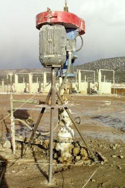
PCPs have successfully deliquified gas wells if equipped with variable-speed drives and the inflow rate was well understood. Some operators have had problems with the motor on a top-drive PCP putting a large, vibrating, cantilevered load on the wellhead pumping tee, but that can be corrected with an adequate support (Fig. 3).
ESPs
Electric submersible pumps (ESPs) are dynamic pumps that use multiple stages to raise the liquid pressure high enough to overcome static head of the discharge column. Historically these pumps were installed in high-volume artificial-lift applications that are seldom appropriate for deliquifying gas wells.
Several manufacturers sell lower-capacity ESPs for deliquification applications. Again, if one knows the inflow rate, pump capacity, and NPSH-a then the pumps can be effective. If the operators allow the NPSH to fall below the NPSH-r (in either gas or oil wells), then the pumps will cavitate and experience the tearing of metal off the pump’s control surfaces.
Gas lift
Gas lift is an effective artificial-lift technique. About 80% of the benefit of gas lift comes from dissolving the lift gas into the oil column and improving the gas-transport characteristics. The remaining 20% of the benefit is simply velocity effects of the gas dragging the oil along with the gas flow.
The ability of oil to absorb gas depends on the crude characteristics, but certain crudes can absorb enough gas to lower their specific gravity by up to 0.1 (15% reduction of the crude’s density).
If the crude has a 55° API gravity (SG = 0.759 relative to water) in a 3,000-ft well, then the hydrostatic head of the column is 980 psig. If the lift gas lowers the gravity by 0.1 (to the equivalent of 84° API), then the column would exert 850 psig.
This 13% reduction in the backpressure is important, but a bigger benefit comes from the undissolved gas creating void spaces that further lower the pressure on the standing valve. The largest benefit comes from the increased gas ability to transport the lower-density liquid.
Water has little ability to absorb natural gas so that one loses that benefit. A water column saturated with gas at 1,300 psig and 70 F. can absorb 0.15% of its mass, reducing the specific gravity only insignificantly.
The second benefit is that void spaces are greater with water than with crude because more free gas is in the column at the same injection rate. But the major benefit of needing to move a lighter liquid is unavailable.
Because absorption is unavailable for deliquification, one only receives 20% of lift gas benefit.
The author’s review of gas-lift applications in several fields determined that gas lift uses five times the power of the other deliquification methods and lift gas is unable to lower bottomhole pressure as much as other methods.
Operators in the Black Warrior basin have reported good success with gas lift in shallow coalbed-methane wells, but the author has not verified those data. Coalbed operators commonly have used some form of gas lift at one time or another. It is one process that everyone has to try. But most often operators use “poor-boy” gas lift in which they inject gas into the tubing-casing annulus without a packer or gas-lift valves.
The author has never found an instance where such gas lift has sustained increases in production, nor has removal of it failed to increase net production.
Jet pumps
Jet pumps have been a niche product in crude production for more than 50 years. These pumps use a high-velocity-liquid flow through a downhole nozzle to draw a suction stream into a throat that opens onto a divergent nozzle to convert the intermediate velocity of the mixed stream to an increased pressure (Fig. 4a).
Oil wells with jet pumps typically have a packer between the tubing and casing so that the power-liquid is pumped down the tubing (for some pump models the liquid is pumped down the annulus) and the combined stream returns up the annulus (or tubing). This means that the entire well production must flow through the pump.
Jet pumps have a lower efficiency than several other methods because they require more input horsepower per barrel of liquid.
Gas-well operators see the lack of moving parts downhole as a significant advantage in deliquification. The problem with this is that the NPSH-r of a jet pump is the highest of any of the artificial-lift devices.
If the NPSH-a falls slightly below the NPSH-r the pump will cavitate (Fig. 2) at the entrance to the throat and the increased roughness of the throat will quickly create enough perturbations in the flow to prevent any suction fluid from moving.
Traditional jet pumps, installed with a packer, are never effective for deliquification because the space required within the pump for commercial gas production requires velocities that ensure the pump will quickly cavitate.
During the last 20 years, manufacturers have developed coiled-tubing jet pumps. These pumps use smaller tubing within the production tubing. These systems pump the power liquid down the small string and through the pump. The pump discharges the combined power-liquid and produced fluids into the tubing-tubing annulus. Produced gas goes up the tubing-casing annulus.
Coiled-tubing jet pumps operate effectively as long as the design matches closely the inflow and pump capacity and the operator maintains the power-fluid pressure within a very narrow range.
The work done by the pump is a function of the power-fluid flow rate and the pump’s discharge pressure. When gas passes through the jet pump, the discharge pressure decreases and the jet pump wants to accept a higher flow rate.
If the jet pump increases the flow rate, indicated on surface by the surface-pump’s discharge pressure decreasing, the risk of cavitation damage increases rapidly. A constant-pressure valve on the surface will reduce the flow rate in this scenario, thereby extending pump life.
Operators can retrieve coiled-tubing pumps from the wellbore by reversing the flow to allow the surface-pump’s discharge pressure to transport the pump to surface. This needs to be done frequently to ensure the maintenance of integrity of the pump internals.
Surfactant injection
Both batch and continuous surfactant injection can effectively increase oil production in some wells.
Activated soap and foamers reduce the hydrostatic head on the formation. Weatherford Corp. has shown that properly constituted foam in appropriate wells can reduce the critical velocity by as much as two-thirds.
Success is rarer in gas wells. One frequent cause of failure is that the soap does not activate.
The turbulence of the multiphase flow generally should cause the soap to activate or foam, but frequently the flow rate at the bottom of the tubing is not strong enough to churn the soap into foam. When this happens, the highly viscous liquid lies on top of the water and restricts flow.
Deliquification technologies
With about 400,000 gas wells in the US and with about 80% experiencing some liquid-loading problems, deliquification is a very active area of research and development. Much of this work involves the adaptation of artificial-lift equipment to deliquification and on techniques that would not be effective for crude-oil production.
Many researchers have evaluated the concept of critical flow and every year a few published papers contain new correlations that refine previous work. This research mostly revisits the data sets from previous authors and it often contains very little new data to support the papers’ conclusions.
Because most work on determining the gas-velocity required to move water as mist successfully has been done at higher pressures than encountered in low-pressure gas wells, none of the correlations is universally reliable for predicting low-pressure well performance and one should be skeptical about the results of these calculations.
None of the techniques and equipment developed specifically for deliquification has an NPSH-r. Each technique discussed in the following sections works with no liquid accumulation in the casing, but several will fail if the liquid-level is too high.
Velocity strings
A smaller flow-conduit allows for higher velocity flow for the same mass flow rate. Higher velocity flow has a better chance of dragging entrained liquid up the wellbore, but higher velocity flow also has a higher pressure drop due to friction.
Replacing a production string with a smaller diameter string can lower flowing bottomhole pressure by removing a hydrostatic head or raise it by increasing friction drop. Operators commonly unload a well with a velocity string and limit the production increases because of the friction drop consideration. Further, small strings are hard to kick off and almost impossible to swab or run downhole tools in.
Wellbore fluids will flow to the path that provides the lowest total pressure drop. Operators frequently look at the pressure differential between the tubing and casing and open the annulus. But it is never a good idea to fully open the annulus on a well that has a velocity string.
For example, assume the well flows above its critical rate in 23⁄8-in. tubing inside 7-in. casing and the tubing-casing differential is 100 psi. Without a fluid column in the well, fluid friction in the tubing causes the entire pressure difference. Because the annulus flow area is 10 times larger than the tubing flow area, the flowing bottomhole pressure will decrease by almost 100 psi (that is, the new friction in the annulus will approach zero).
This will result in a very low velocity in the tubing, which is equal to the mass flow rate that yields a friction drop of nearly zero. In this case, unloading will stop and the well will start to load.
Plungers
A plunger eliminates interfacial slip by separating the liquid from the gas. Plungers can work effectively in lifting small amounts of liquid from wells that have enough energy for lifting the weight of the plunger and liquid.
A plunger will stop working usually because too much liquid accumulates above it, corrosion or scale have blocked the plunger’s path, or the differential pressure between the flowing bottomhole and the tubinghead pressures is too low for the gas to lift the plunger.
With analysis, operators can correct these problems but a plunger is never a set-and-forget type of deliquification method.
Common trends include progressive plungers, two-piece plungers, and setting velocity low-limits for the higher leakage plungers.
Plungers are a staple deliquification technique most onshore gas fields and operators in continue to improve their understanding of effective plunger use.
Ejectors
Like jet pumps, ejectors are thermo-compressors that transfer momentum from a high-velocity stream to a low-velocity stream and then convert the intermediate velocity to pressure in a divergent nozzle (Fig. 4b).
Jet pumps are eductors designed for incompressible fluids. Ejectors have a set of convergent-divergent nozzles to accommodate compressible fluids both for power-fluid and on the suction side.
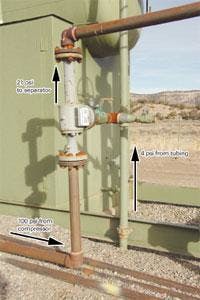
An ejector in deliquification uses a high-pressure gas, either from a wellsite compressor or a nearby high-pressure well, to lower the tubing pressure on a well. The ejector is at a convenient surface location (Fig. 5) and the technology requires no downhole equipment.
An ejector designed for a suction-flow above a critical velocity on a tubing string will keep a well unloaded, while the well produces most of the flow, at much lower velocities, up the tubing-casing annulus.
Wells with this configuration can exhibit liquid levels at or below the end of the tubing for years of stable production.
Vortex tools
Vortex tools are downhole devices to force a rotating flow profile that tends to sling liquid water to the outside of the tubing, allowing nearly single-phase flow within a rotating liquid.
These tools have lowered the critical rate by as much as 30%.
Evaporation
Fig. 20-4 in the GPSA Engineering Data Book shows clearly that as pressure decreases, water evaporation increases, thereby dramatically increasing water vapor.
Because a reservoir’s temperature is generally constant, lowering the pressure from 200 psig to 25 psig at a constant 150 F. will increase water content of the gas flow from 800 lbm/MMcf to 8,000 lbm/MMcf.
The 8,000 lbm is more than 20 bbl/MMcf of water, so that as wellhead pressure decreases the well will produce water as water vapor. Water vapor is a gas and not a two-phase mist; therefore no interfacial inefficiencies exist and deliquification does not have to consider the velocity of the vapor.
Any low-pressure operation needs to consider evaporation as a major, often a primary, means of deliquification.
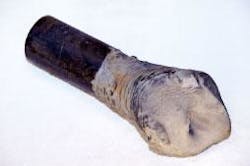
Produced water is not pure. The flow will not transport the dissolved solids with the water vapor. For a well that produces 10,000 mg/l. total dissolved solids (TDS), every barrel of water that evaporates will deposit 3.5 lb of solids (Fig. 6). This phase-change scale may cause a major problem with plugging in wellbore tubulars, perforations, or within the reservoir.
A program that relies on evaporation for deliquification needs to include a plan for evaluation and mitigation of phase-change scale.
Phase-change scale (or salt) in gas operations is a difficult problem. The industry has faced salt problems in oil wells for decades and has effective treatments to prevent the accumulation of phase-change scale. All these treatments react with common salts and the continuous-phase liquids can remove and carry away the soft products of these reactions.
A stream that is predominantly gas rarely has a continuous-phase liquid; therefore, addition of salt-mitigation chemicals to a gas stream frequently results in an accumulation of immobile sludge instead of solids.
With no preventive treatment for phase-change scale in gas wells, the next-best approach is to closely monitor calibrated and appropriate instruments to determine blockages.
Hot water or acid flushes, as well as salt-mitigation chemicals in these flushes, can remove salt blocks from a pipe or vessel.
Tubing-flow controller
The problems with velocity strings are not insurmountable. One effective technique puts a control valve on the tubing-casing annulus and a flow-measurement device on the tubing. A programmable-logic controller (PLC) can throttle the casing valve to maintain the velocity in the tubing high enough to ensure continuous lifting of water.
Operators have had mixed success with tubing-flow controllers.
These devices typically use square-edged orifice or v-cone flow-measurement and pneumatic-operated control valves. The flow measurement devices translate a differential pressure across a known restriction into a volume flow rate and the differential pressure increases when flow increases.
Many wells with this technique may load up because of the imprecision in the positioning of the control valve (a very small change in valve position is a very large change in casing flow) and the imposed backpressure from the flow-restriction acting together to impart a positive feedback loop.
Recently one company has replaced the differential-pressure, flow-measurement device with a pitot tube that imparts a smaller backpressure on the well. They also replaced the pneumatic control-valve with an electric-driven control valve with precise control and a linear flow-response to valve-position. Early results indicate a consistent, repeatable, and predictable performance for the device.✦
The author
David Simpson (zdas04@ muleshoe-eng.com) is the proprietor and principal engineer of MuleShoe Engineering, Fora Vista, NM. He primarily is involved in coalbed methane, low-pressure operations, gas compression, gas measurement, oil field construction, gas well deliquification, and project management. Simpson has a BS is industrial management from the University of Arkansas, Fayetteville, and an MS in mechanical engineering from the University of Colorado, Denver. He is an SPE member.
