New technique calculates borehole curvature, torsion
Wellbore curvature and torsion greatly influence the forces applied on the downhole pipe string and its consequent deformation. They serve as the bases for calculating the drag and torque of a pipe string and checking its strength and also serve as indices to evaluate the quality of a well trajectory. Accordingly, curvature and torsion affect well drilling and completion, production, and even workover operations.
It’s necessary to accurately calculate and describe the shape of a wellbore trajectory in order to monitor and control it effectively. A wellbore trajectory is a continuous and smooth curve in space, which bends (builds or drops) and turns simultaneously.
The industry has recognized the importance of borehole curvature for more than 50 years and has widely applied the research results in the field. Engineers have done very little research, however, on borehole torsion.
This article models a moving frame on a wellbore trajectory, gives its equation and establishes contact with the wellbore trajectory, and presents a new method to describe the shape of wellbore trajectory in space.
From the point of view of kinematics, the article gives the law of frame’s motion while moving along wellbore trajectory and the kinematic meanings of borehole curvature and torsion, thus revealing the intrinsic relationship and basic characteristic of various parameters of wellbore trajectories.
The method and equations discussed provide mathematically consistent techniques, not only for planned well paths, but also for survey calculations.
Inclination, azimuth
Originally, the oil and gas industry was focused on drilling vertical wells. The concept of inclination angle arose when engineers realized that a drilled trajectory is not a plumb line. Then the concept of azimuth angle came into being when they further understood that a drilled trajectory does not change in a vertical plane.
We can describe the change in direction of a well trajectory by means of inclination angle and azimuth angle, but the curvature is also significant, as it greatly affects well drilling, completion, and even production.
Over the past 50 years, the drilling industry has engaged in a lot of research related to the problem of borehole curvature.1-11 In 1957, Lubinski published a now well-known formula to calculate dogleg angle and its nomogram.1 In 1968, Wilson introduced the radius-of-curvature method and a formula to calculate the curvature of a drilled trajectory.4
The primary parameters related to wellbore trajectory curvature are bending angle (dogleg angle) and borehole curvature. In order to calculate and analyze them, researchers have provided analytic methods, diagram-searching methods, graphic methods, and the Ouija board method.
Although the last three methods show considerable error and are inconvenient to use, they were commonly used into the 1980s. Today, the analytic method is the most often used to calculate the bending angle and curvature of a well trajectory.
A wellbore trajectory is simply a curve in space, which bends and turns simultaneously to change direction. Research shows that the extensive turning of a well trajectory may twist a downhole pipe string, greatly increasing the forces applied to the string and causing deformation.5
In 1983, E.E. Fitchard and S.A. Fitchard introduced a formula to calculate borehole torsion applied to a cylindrical helix trajectory (OGJ, Jan. 17, 1983, pp. 121-124). In the following 10 years, there was little additional research on borehole torsion.
Since 1992, we have systematically studied the curvature and torsion of wellbore trajectories in space using differential geometry.5 7-11 Through establishing a moving frame on wellbore trajectory and contacting it with the trajectory’s equation, we introduce a new perspective and method to describe the shape of wellbore trajectory in space. From the perspective of differential geometry, this expands the definitions and geometric meanings of bending angle, borehole curvature, torsion angle, and borehole torsion.
This work verifies the research results provided by A. Lubinski and G.J. Wilson with regard to wellbore curvature, and presents general equations to determine torsion angle and borehole torsion.5 7 10 It also includes concrete calculation formulae for various typical models of wellbore trajectory, revealing the intrinsic relationship and characteristics of the various parameters of wellbore trajectory.
With regard to survey calculations, this author and colleagues proposed the curve structure method based on the bending and turning parameters of wellbore trajectory9 10 and researched the calculation method to determine the average borehole curvature over a survey interval.11
In addition, we investigated the law of frame’s motion while moving along a wellbore trajectory from the point of view of kinematics and provide the kinematic meanings of borehole curvature and torsion.
Moving frame
As mentioned, a wellbore trajectory is a continuous and smooth curve in space, bending and turning simultaneously to change direction. There are some intrinsic relations between the parameters that serve as the basis of describing and calculating a well trajectory.
Basic equation
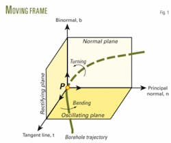
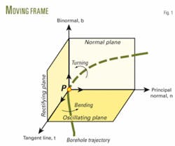
Draw a tangent line across a given point P on a well trajectory and intercept a unit length on the tangent line as unit tangent vector t; it points in the onward direction of the well trajectory (Fig. 1). Next, draw a unit vector in the bending direction of the well trajectory as unit principal normal vector n; it points in the concave direction of well trajectory.
Again, draw a unit vector perpendicular to both t and n as binormal vector b, viz. b = t × n. The three unit vectors form a right-hand system and constitute the moving frame of well trajectory at point P,5 7 9 10 also known as “Frenet’s frame.”12 13
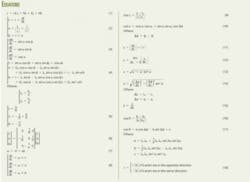
Finding out the relation between the moving frame and well trajectory requires embodying the equation of the moving frame. Equation 1 defines the well trajectory in vector form (accompanying box). According to differential geometry,12 13 Equation 2 expresses the relationship among unit tangent vector t, unit principal normal vector n, unit binormal vector b, and displacement vector r of well trajectory.
Thus, the moving frame is in combination with the equation of well trajectory, which makes it feasible to describe the curvature and torsion of well trajectory in space by virtue of the moving frame (Fig. 2).
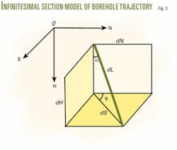
According to the differential model of wellbore trajectory, Equation 3 gives the relation between coordinate increments and curved-section length, inclination angle, and azimuth angle for a tiny interval. Substituting Equations 1 and 3 into Equation 2 yields Equation 4, which is the vector equation of moving frame on a well trajectory.
Kinematics equation
One can form a moving frame at any point P on a well trajectory. From the point of view of kinematics, when the point P moves along the well trajectory, the moving frame will move concordantly with it. It has been mathematically proven that Equation 5 or 6, viz. Frenet’s equation, can depict the movement behavior of a moving frame.12 13
That is to say, the derivatives of unit vector t, n, and b with respect to measured depth L can be expressed with linear combination of vector t, n, and b. In this way, combining Equation 5 or 6 with Equation 2 depicts the law of frame’s motion while the point P moves along a wellbore trajectory (Fig. 3).
One can regard a moving frame as a rigid body turning around the point P, while it moves along a well trajectory. According to the principle of kinematics, Equation 7 indicates instantaneous rotational velocity of the moving frame in vector form. The vector of instantaneous rotational velocity is called Darboux’s vector and lies in the rectifying plane and can be disassembled to two components τt and κb.
Thus, one can regard the instantaneous rotational velocity of moving frame as the sum of two kinds of rotations, namely, rotating around the axis in the τt direction and around the axis in the κb direction. Therefore, the kinematics meaning of borehole curvature and torsion become explicit: Borehole curvature equals the component of moving frame rotating around the binormal, and borehole torsion equals the component of moving frame around the tangent line. In addition, Equation 8 gives Frenet’s equation in another form.
Borehole curvature
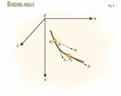
The industry defines the included angle between two tangent vectors of wellbore trajectory at different two points as dogleg angle.1-4 Generally, these two tangent vectors are not in the same plane, so that dogleg angle displays as a space angle (Fig. 4). Dogleg angle is also named as overall angle, which means that it includes both inclination change and azimuth change. In mathematics and drilling engineering, this is called the bending angle.
According to the definition of bending angle, Equation 9 calculates the bending angle between two points on wellbore trajectory. Substituting Equation 4 into Equation 9 yields Equation 10, which is identical with that given by Lubinski.1
Borehole curvature, representing the extent of a well trajectory’s departure from a straight line, is the rate that the tangent vector of well trajectory rotates with respect to curved length. It depicts the bending extent of a wellbore trajectory. Equation 11, a definitive expression of borehole curvature, demonstrates that the rotating rate of the tangent vector with respect to curved length describes the bending extent of wellbore trajectory when a given point moves forward along a well trajectory.
Besides being an important index to check buildup rates on the bottomhole assembly (BHA), understanding the deflection behavior of the formation, and evaluating a wellbore trajectory’s quality, borehole curvature serves as the basis for monitoring a drilled wellbore’s trajectory and calculating the forces applied on the drillstring and its deformation. Deciding whether to trip pipe and having the ability to run casing smoothly and successfully depends on borehole curvature; it is therefore a significant factor for safe, quick, and efficient drilling.
There are two ways of deducing the applied formula for calculating borehole curvature.5 7 8 One is to substitute the expression of unit tangent vector, t, from Equation 4 into Equation 11, another is to substitute the formula of bending angle, from Equation 10 into Equation 12, another definitive expression of borehole curvature. Through mathematical deduction, both methods yield Equation 13, which is the same as that presented by Wilson.4 But it is necessary to point out that Equation 13 applies to calculate the borehole curvature at a given point.
Average curvature
During the process of drilling, engineers usually pay attention to the average curvature of a survey interval. Generally, borehole curvature varies with measured depth rather than a constant, which is the reason for calculating average curvature. At present, Equations 14 and 15 are popularly used to calculate the average curvature of a survey interval.
In order to calculate the average curvature scientifically and reasonably, the author draws the following conclusions based on theoretical analyses and lots of example calculation:11
- In most cases, Equations 5 and 6 yield very similar results. Thus, it is acceptable to use either formula for calculating the average curvature of a survey interval.
- For natural-curve trajectories and cylinder-helix trajectories, the value of average inclination angle for a survey interval equals that of inclination angle at the midpoint as inclination angle is linear functions vs. measured depth. Thus, the result from Equation 14 actually represents the value of borehole curvature at the midpoints for natural-curve trajectories and cylinder-helix trajectories.
- It has been proven that Equation 15 fully conforms to spatial-arc model in theory7 and verified with actual data.11
- There always exists some error when using Equation 14 to calculate the average curvature of a spatial-arc interval. The bigger and ∆L are, the larger the error. Except for ω = 0° or ω = 180°, errors exist at other tool face angles, and the biggest one may be beyond 60%.11
In conclusion, Equation 14 is a formula for calculating borehole curvature at a given point. It sometimes shows considerable error to calculate the average curvature of a survey interval through substituting average values of interval parameters into Equation 14.
Equation 15, however, is deduced from the mathematical definition of borehole curvature and is more reasonable in terms of theoretical analyses and calculated results. Therefore, the author recommends using Equation 15 to calculate the average curvature of a survey interval.
Borehole torsion
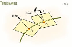
The industry defines the included angle between two binormal vectors of wellbore trajectory at different two points in its onward direction as the torsion angle (Fig. 5).5 7 According to the definition of the included angle between two vectors, Equation 16 gives the torsion angle between the two given points on a wellbore trajectory. Substituting Equation 4 into Equation 16 yields Equation 17, which is the formula for calculating the torsion angle.
It is necessary to point out that bending angle cannot directly express the bending extent of a wellbore trajectory. Nevertheless, as an important indirect parameter, use of bending angle can simplify the calculation method and process of planning well path and performing survey calculations. In the same way, torsion angle is not a direct parameter of expressing torsion extent of a wellbore trajectory.
Borehole torsion, illustrating the extent of well trajectory’s departure from a plane curve, is the rotating rate that the binormal vector of well trajectory rotates with respect to curved length. It depicts the torsion extent of wellbore trajectory.5 7 Equation 18 is the definition expression of borehole torsion.
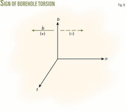
The symbolic meaning of borehole torsion: when a point moves along a wellbore trajectory in the onward direction, if the derivative of unit binormal vector with respect to measured depth, •b , is in the opposite direction of unit principal normal vector n, the sign of borehole torsion, , is positive. Otherwise, the sign of is negative (Fig. 6).
Substituting the expression of unit binormal vector b in Equation 4 into Equation 18 yields Equation 19, which is the formula that calculates the borehole torsion at a given point.
The value of borehole curvature is constantly positive, but that of borehole torsion can be positive or negative. A zero borehole curvature, = 0, will depict a straight section and a zero borehole torsion, = 0, will depict a plane curve.
Equations 17 and 19, universal formulas for torsion angle and borehole torsion, respectively, can be simplified for given mathematical models of wellbore trajectory. Equations 20-23 give the simplified formulas for spatial-arc trajectory, natural-curve trajectory, cylinder-helix trajectory, and constant-tool-face trajectory, respectively. The formula for borehole torsion presented in this article is different from that given by Fitchard and Fitchard for cylinder-helix trajectory (OGJ, Jan. 17, 1983, pp. 121-124).
Learnings
This study has led the author to conclude:
- In research on the shape of a wellbore trajectory, the wellbore trajectory described by spatial-arc model is a sort of plane curve that borehole torsion is zero, i.e., no tortuous behavior.
- Azimuth change is a prerequisite to the existence of borehole torsion. If azimuth angle remains constant, borehole torsion will be zero.
- For the natural-curve model, cylinder-helix model, and constant-tool-face model, borehole torsion is a function of inclination angle when the characteristic parameters of a well trajectory are determined.
Example
An example calculates the torsion parameters of a well trajectory, given the following input data:
- Length of survey interval: ∆L1,2 = 30 m.
- Inclination at the upper survey station: 1 = 20°.
- Inclination at the lower survey station: 2 = 30°.
- Azimuth change: ∆1,2 = -10°.
As mentioned, there is no torsion in the spatial-arc model, and there exists the same law of inclination change in natural-curve model, cylinder-helix model, and constant-tool-face model. Therefore, azimuth angle, torsion angle, and borehole torsion vary with measured depth or inclination angle. Table 1 shows the calculated results.
With regard to a survey interval of a drilled well trajectory or a section of a planned well path, one must calculate the average borehole torsion. With the definition of borehole torsion and the calculation method of average borehole curvature as a reference, the formula for calculating average borehole torsion will be similar to Equation 15. Thus, Equation 24 gives the formula to calculate average borehole torsion as the value of torsion angle is always positive and that of borehole torsion can be positive or negative.
Calculating borehole curvature and torsion provides a basis for effectively monitoring and controlling wellbore trajectories, analyzing the forces applied on drilling string and its deformation, calculating drag and torque of pipe string and checking its strength.14 15 Therefore, applying these results can produce higher well trajectory quality, and result in safer, faster, and more efficient drilling.
References
- Lubinski, A., “How to Determine Hole Curvature,” The Petroleum Engineer, February 1957, pp. 42-47.
- Lubinski, A., “Maximum Permissible Dog-Legs in Rotary Boreholes,” Journal of Petroleum Technology, February 1961, pp. 175-194.
- Wilson, G.J., “Dog-Leg Control in Directional Drilled Wells,” Journal of Petroleum Technology, January 1967, pp. 107-112.
- Wilson, G.J., “An Improved Method for Computing Directional Surveys,” Journal of Petroleum Technology, August 1968, pp. 871-876.
- Shan, W., Xiushan, L., Daqian, Z., et al., “The Shape of the Space Curve of Borehole Trajectory,” Journal of Daqing Petroleum Institute, September 1993, Vol. 17, No. 3, pp. 32-36.
- Fitchard, E.E., and Fitchard, S.A., “The Effect of Torsion on Borehole Curvature,” OGJ, Jan. 17, 1983, pp. 121-124.
- Xiushan, L., Shan, W., Zhongxuan, J., et al., Designing Theory and Describing Method for Wellbore Trajectory, Heilongjiang Science and Technology Press, Harbin, China, 1993.
- Xiushan, L., Daqian, Z., Lin, Q., “Accurate Description of Curved shape in Space for an Actual Borehole Trajectory,” Petroleum Drilling Techniques, Dezhou, China, June 1992, Vol. 20, No. 2, pp. 18-20.
- Xiushan, L., Zaihong, S., Daqian, Z., “The Curve Structure Method of Borehole Trajectory Calculation,” Acta Petrolei Sinica, Beijing, July 1994, Vol. 15, No.3, pp. 126-33.
- Xiushan, L., and Zaihong, S., “Numerical Approximation Improves Well Survey Calculation,” OGJ, Apr. 9, 2001, pp. 50-54.
- Xiushan, L., “Average Borehole Curvature Calculation of Hole Trajectory,” Oil Drilling & Production Technology, October 2005, Vol. 27, No. 5, pp. 11-15.
- John Oprea, “Differential Geometry and Its Applications (2nd Edition),” Prentice Hall, 2003.
- Xiangming, M., and Jingzhi, H., “Differential Geometry (3rd Edition),” Higher Education Press, Beijing, 2003.
- Walker, B.H., and Friedman, M.B., “Three-Dimensional Force and Deflection Analysis of a Variable Cross Section Drill String,” Journal of Pressure Vessel Technology, May 1977, pp. 367-373.
- H-S. Ho, “An Improved Modeling Program for Computing the Torque and Drag in Directional and Deep Wells,” SPE paper No. 18047, SPE Annual Technical Conference and Exhibition, Houston, Oct. 2-5, 1988.
The author
Xiushan Liu (xiushanliu @sina.com) is a professor and deputy director of the petroleum drilling research institute at Sinopec Corp.’s Exploration & Production Research Institute, a visiting professor at CNPC’s Key Laboratory of Drilling Engineering, and a part-time professor at Daqing Petroleum Institute in China. He has a BS and an MS from Daqing Petroleum Institute and a PhD from Research Institute of Petroleum Exploration & Development of CNPC, all in petroleum engineering. Liu is a member of SPE.
