SPECIAL REPORT: Deepwater fluid displacement needs special approaches
Techniques that consider all the chemical and mechanical aspects of displacing drilling fluid can benefit dramatically the economics and effectiveness of well completions in deep water. Three critical components to consider include spacer design, wellbore cleanup efficiency, and fluid selection.
With day rates for deepwater rigs at unprecedented high levels, the time saved during fluid displacement can reduce overall project cost. A correctly engineered and executed displacement operation avoids having to repeat the process to rectify chemical and mechanical problems that may occur during improperly designed transitions. Correct procedures are important especially in openhole completions.
Literature documents extensively the need of proper techniques for replacing drilling fluid with completion brine and thoroughly cleaning the wellbore.1-4 An effective displacement is one that removes completely on the first attempt all drilling fluid, residual mud solids, and mud film trapped on the casing and tubular walls. Failure to do so can contaminate the completion fluid, risk mechanical problems, and restrict hydrocarbon flow.
Repeating the process to correct inadequate displacement will increase rig time and costs considerably, especially for deepwater completions.5 6
Traditional displacement
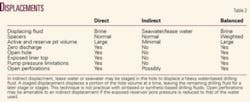
Whether the displacement is direct, indirect, or balanced, the displacement process usually includes a series of chemical spacers followed by brine, drill water, or seawater. Selection of the displacement fluid directly affects fluid handling on surface and the fluid volumes that may have to be disposed of off-location.
Selection decisions will consider the required pit space volume on the rig, cheap water source availability, wellbore ability to withstand the pressure differential between the water and drilling mud columns, and pump pressures required for the displacement.
The direct method displaces the drilling fluid with cleaning spacers followed by completion fluid. This method is preferable in zero discharge areas where minimizing fluid waste is critical or when handling brine and mud on the surface at the same time is possible.
Direct displacement requires the availability on surface of a brine volume equal to the entire hole volume and the rig capacity to handle the displaced mud. Logistics are critical to the success of direct displacement. Technical capability and chemical availability have made the method suitable for most displacement applications that have manageable mud and brine handling means.
The indirect method displaces mud with cleaning spacers followed by a hole-volume of water. Completion fluid later displaces the water from the hole.
Some operators prefer indirect displacement because it allows for repeated flushing of the casing until clean with inexpensive seawater or drill water, which does not require filtering and usually can be discharged.
Unacceptable differential or pump pressure, however, may not permit filling the hole with seawater or drill water. Furthermore, exposing a liner top, open perforations, or openhole to the negative differential of seawater or drill water relative to a mud column may not be prudent. Consequently, these cases require a balanced or near-balanced method.
The balanced method essentially is another type of direct displacement. In this case, weighted spacers balance the mud column, thereby minimizing the differential pressures during the pumping of the displacement fluid.
For example, low-density spacers in seawater may require pump pressure during circulation that exceeds the formation fracture pressure or the pressure that an exposed liner top will tolerate before breaking down. Moreover, these spacers may apply insufficient hydrostatic pressure to hold back the formation during the displacement.
Weighted spacers to a balanced or near-balanced condition until the total hydrostatic pressure equals or nearly equals the formation or liner-top pressure reduces the pump pressure required to move the spacers around the hole. In addition, balanced or near-balanced weighted spacers will facilitate well control by maintaining constant pressure on the reservoir.
Spacer systems differ depending on whether the displacement involves oil-based mud (OBM), synthetic-based (SBM), or water-based mud (WBM). Displacements of OBM and SBM use solvent and surfactant chemistry as the primary cleaning agents, while WBM displacements use caustic solutions and water-wetting surfactants.
In either case, the spacers are designed for a specific function, such as:
- Physically move or dislodge the drilling mud.
- Clean the mud film from the tubulars and casing, leaving them water-wet.
The spacer must be compatible with the drilling mud being displaced. With the exception of openhole displacements, where it may be desirable to leave the mud filter cake intact, the spacers should remove all trace of the mud from the wellbore.
Tables 1 and 2 list the function and qualities of typical spacers used in a direct or indirect displacement.
null
Deepwater demands
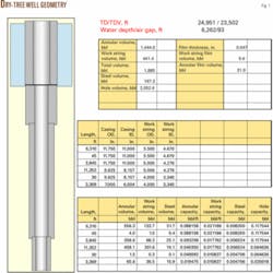
Deepwater completions are either dry or wet tree (subsea), with the dry-tree completions usually conducted from a moored tension-leg platform (TLP) or spar-type platform. Dry-tree completions have production-sized casing run from the platform to the seafloor (Fig. 1).
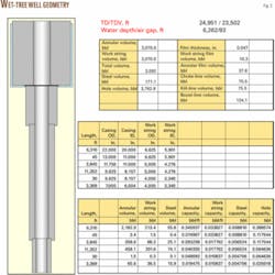
Subsea completions involve large (about 20-in. ID) riser pipe that runs from the mud line to the offshore vessel from which operations are conducted (Fig. 2). This large riser pipe and the auxiliary lines that attach to the blowout preventers (BOPs) complicate the displacement process for subsea-completed wells.
Regardless of completion type, the low mud-line temperature in deepwater affects significantly both fluid selection and spacer chemistry performance. The job design, therefore, must consider how a wide temperature range that may vary by 200° F. affects both spacer size and cleaning efficiency.
In deep water, the drilling riser may have three and four times the capacity of the casing below the mud line. To attain minimum contact time, the riser annulus must have larger spacers than the same spacers used for cleaning the casing. Also, the riser spacers need much higher pump rates to achieve turbulent flow.
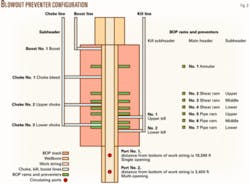
Cleaning the riser as well as the production casing, the choke and kill lines, the boost line, bleed-off lines, and the subsea BOP stack requires special attention (Fig. 3). The procedure should include fresh spacers to clean drilling mud and residual solids from the choke, kill, and boost lines. Failure to use fresh spacers risks circulating dirty or black water or whole mud into the surface system and filtration equipment.
The volume of viscous weighted transition spacer should equal 10% of the volume being displaced from the drill pipe and casing annulus, drill pipe and riser annulus, and other areas. The displacement design can base the size of the cleaning or wash spacer on the results from cleaning efficiency test described as follows.
To optimize the cleaning process, the subsea deepwater displacement should have three stages: casing and liner, riser, and auxiliary (choke, kill, and boost) lines.
Because it is always desirable to have pipe rotation during the displacement, pipe rams and annular preventers should remain open while the casing and liner are being displaced. This requires that the riser annulus accommodates the returns.
Once the spacers and displacing fluid have entered the riser, the next stage displaces the fluids in the riser with fluids pumped down the drill pipe and auxiliary lines. The last stage cleans the auxiliary lines, with rams and preventers closed.
True crystallization temperature (TCT) is rarely a problem under the dynamic conditions of a mud-to-brine displacement. The design should base its selection of the displacement fluids, however, including the completion brine, on the fluid’s ability to keep salts in solution below the lowest temperature in the well at the mud line. Because pressure tends to increase the TCT of some salt brines, the design must consider pressure crystallization (PCT) effects.
Deepwater applications often include completion brines with a TCT of 11-15° F. lower than usual for a given temperature to compensate for pressure effects, such as that seen during a BOP test.7
Subsea openhole completions
Openhole completions are common in shallow-water (less than 1,000 ft) and recently have become more common in the deep water.
These completions require balanced fluid weight with reservoir pressure so that fluids will not enter the well because of underbalance or break down the formation because of overbalance.
A very narrow window between reservoir pore pressure and reservoir fracture pressure may exist in shallow gas openhole completions. Accordingly, the reservoir drill-in (RDF) and completion fluids must work within those limits.
Prior to drilling the pay sand, the drilling operation may use an RDF to displace the drilling mud after drilling out of the casing shoe. In this instance, an RDF will be used to drill the openhole section. This is followed usually by displacing the RDF from the openhole with a solid-free version of a base fluid identical to RDF. This guarantees compatibility with the formation and is intended to maintain the filter cake integrity and minimize fluid losses.
The operation must maintain compatibility between the drilling mud and RDF, the mud and completion brine, and the RDF and completion brine. Fluids circulated into the openhole also must be compatible with fluids already in place, formation fluids, and formation mineralogy.
Laboratory tests should confirm that the displacing fluids will not emulsify or sludge with the mud or RDF in the openhole or with the formation water or crude. To prevent swelling or dispersion, the design should select an RDF and completion brine based on shale stability and clay inhibition.
Furthermore, the potential for the formation of gas hydrates is a critical consideration when engineering a subsea openhole displacement. Mixing methane or other hydrocarbon gas with water under low temperature and high pressure during extended shut-in periods can initiate the formation of gas hydrate.
In openhole displacements, this condition may arise if there is a shutdown during displacement or if there are trapped fluids in a dead area, such as an isolated riser, choke, or kill line. When the well has an acute potential for gas-hydrate formation, brine selection is crucial and the displacement fluid must contain sufficient salt or other hydrate inhibitor.
Openhole displacements usually have two stages: displacing the drilling mud or RDF out of the openhole, and displacing the drilling mud or RDF out of the casing. In most cases, a completion brine will follow the casing displacement spacers. This requires balanced fluid density, pressure maintenance below fracture gradient during displacement, spacers that will not erode the filter cake in the openhole, and compatibility of spacers and completion fluid with either the drilling mud or RDF and formation fluids.
For subsea openhole completions, the well fluids must maintain a balanced pressure on the reservoir throughout the displacement. The hydrostatic density of the fluid column both during displacement and the fluid left in the hole after displacement needs to be sufficient to control formation pressure and prevent fluid ingress into the openhole.
This usually will require a direct displacement of the production casing or weighted spacers that contain solids or are heavy clear brine fluids
For risers isolated for separate cleaning, the operation must make sure that the hydrostatic pressure remaining on the openhole is sufficient to prevent the reservoir from releasing formation liquids or gases. Failure to do so can create conditions favorable to hydrate formation or result in other well control problems.
Another preference is keeping an active riser annulus during displacement of the casing above the openhole. This allows rotating the drill pipe during the displacement.
Spacer chemistry
One should not assume that a cleaning additive blended in seawater, drill water, or brine will clean mud from tubulars and casing. Cleaning efficiencies change with mud type, base brine, additive concentration, pump rate, and contact time.
In deepwater, temperature plays a vital role. A spacer design may not be as effective at the deepwater mud line temperature of 40° F. as at the bottomhole temperature of 200° F. or warmer.
In most cases involving removal of oil or synthetic-based fluids, the cleaning spacer should consist of separate and consecutive stages, comprising a solvent in seawater or brine and a surfactant in seawater or brine. Dispersions of 10-20% solvent in seawater or brine are effective at removing mud solids and debris. A polishing solution of 3-10% surfactant is sufficient to remove oil-wet film and water-wet tubulars.
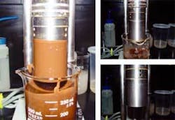
Fig. 4 displays laboratory tests that determine cleaning efficiency in OBM or SMB displacement spacers.
During direct displacements of high-weight mud, the cleaning spacer may require weighting to near mud weight, either to enable sufficient pump rate at acceptable pump pressure or lessen the negative differential pressure on a liner, perforations, or openhole. Because the cleaning spacer cannot include barite solids for weighting up, it has to use high-density brine.
The laboratory tests described previously have shown that surfactant-solvent combinations usually are more effective when blended in base brine containing free water rather than in salt-saturated solutions. On the other hand, it has also been noted that a surfactant added to saturated brine that has been cut back with water may increase viscosity when the spacer picks up drilling mud. This added viscosity acts to block further mud removal. Prior testing on the mud and surfactant or surfactant-solvent spacer can determine if the additive will have the desired effect.
The activity of spacer chemicals changes with temperature. The cleaning efficiency of solvents and surfactants may not be as great at 40° F. as at 150° F. Accordingly, the procedures should include testing the solvents, surfactants, and their blends against the mud and crude at lower temperatures to ensure cleaning efficiency in deepwater displacement applications.
Mechanical displacement aids
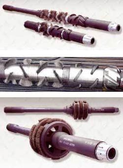
Typically, the cleanout string run to bottom prior to the displacement will include casing brushes and scrapers (Fig. 5). In holes deviated 30° or more from vertical, brushes and scrapers play an essential role in disturbing mud pockets that will form on the low-side of the casing. These tools can remove mechanically mud solids from the casing wall as a precursor to the chemical sweeps and washes that push the mud from the hole.
The usual string includes one scraper spaced out to land at the bottom of each string of casing or liner and one or several brushes spaced out in each size string, depending on the string length.
In a short-trip, the procedure involves pulling the pipe until the top brush is exposed at the surface; at that point, brushes spaced throughout the drillstring will have swept across each foot of casing as they come up the hole. The clean-up string run back to bottom completes the short-trip.
Often the job will also involve reciprocating the scrapers to remove cement or scale across intervals where packers will be set or perforations made.
In deepwater displacements, the procedure will incorporate riser brushes for sweeping the riser annulus and a jetting tool placed across the BOP stack for flushing mud, water, or brine at high flow rates into hard-to-access pockets of the stack body. The indirect method often includes jetting after the displacement to seawater.
Other mechanical aids used in the displacement string are bits and mills, junk baskets for carrying debris out of the hole, and magnets for capturing and transporting to surface large metal cuttings.
References
- Sanchez, R.A., et al., “Effect of Drillpipe Rotation on Hole Cleaning During Directional-Well Drilling,” SPEJ, June 1999.
- Power, D.J., et al., “Drilling Practices and Sweep Selection for Efficient Hole Cleaning in Deviated Wellbores,” Paper No. IADC/SPE 62794, IADC/SPE Asia Pacific Drilling Technology Conference, Kuala Lumpur, Sept. 11-13, 2000.
- Saasen, A., and Løklingholm, G., “The Effect of Drilling Fluid Rheological Properties on Hole Cleaning,” Paper No. IADC/SPE 74558, IADC/SPE Drilling Conference, Dallas, Feb. 26-28, 2000.
- Guillot, D., et al., “Design Rules and Associated Spacer Properties for Optimal Mud Removal in Eccentric Annuli,” Paper No. SPE 21594, International Technical Meeting of the Petroleum Society of CIM/SPE, Calgary, June 10-13, 1990.
- Darring, M.T., et al., “Minor Modifications Make Major Differences in Remote Deepwater-Mud Displacement Operations,” SPE Drilling & Completion, March 2005.
- Messler, D., et al., “Improved Techniques of Deepwater SBM Displacements: A Case History,” Paper No. SPE 73711, SPE International Symposium and Exhibition on Formation Damage Control, Lafayette, La., Feb. 20-21, 2002.
- Freeman, Michael A., et al., “High Pressure Crystallization of Deep-Water Completion Brines,” Paper No. SPE 57829, SPE International Symposium on Formation Damage, Lafayette, La., Feb. 23-24, 2000.
The authors
Syed Ali ([email protected]) is a research consultant for Chevron Energy Technology Co., Houston. He specializes in sandstone acidizing, formation damage control, rock-fluid interaction, mineralogy, and oil field chemistry. Ali holds an MS from Ohio State University and a PhD from Rensselaer Polytechnic Institute, Troy, NY. He serves as an executive editor for SPE Production & Operations.
Michael T. Darring is Southern US Region technical service manager for completion fluids for M-I SWACO and is based in the New Orleans technical center. Darring has held operations and management positions in various fields of completion technology. Darring has a BA in philosophy from the University of Tennessee.


