Crude measurements require tight control
Uncertainties exist in net test results for measurement systems, caused by disparities in the measurement of water content and density. Poorly mixed pipelines, poor density measurement loops, and poor application of sampling technology create these uncertainties.
These errors may not lead to real physical losses. But if the potential for such losses exist, it is imperative that both the defined ends of the measurement chain apply technology with the least possible uncertainty to eliminate their process from any disputes.
Piecemeal improvement in measurement consistency is unlikely to lead to reduced uncertainty. All systems installed should be subject to a proving test of preference meeting the highest possible standard, such as ISO 3171.
While the metering process has always featured sampling systems, many metering systems have been modified to incorporate density compensation to yield total mass, water-in-oil monitors (OWD), or both. Integrated systems are now called “quality measurement systems.”
Many loss controllers, however, pay the price for poor measurement through claims, creating a strong commercial reason to get measurement right. Since ships export much of the oil produced globally, buyers are bound to compare their received and loaded cargos, using accurate and proven sampling systems to minimize the chance of in-transit losses.
When there is a significant difference between the received cargo volume and that stated on the bill of lading, the buyer’s agent will initially protest to the shipper. Unless the shipper accepts liability for the claim, the buyer’s next recourse is to challenge the loading port (seller’s agent).
Any claim will eventually fall to the facility whose measurement is most easily challenged. If both load and receipt port can show that they have proven and traceable sampling operations, conforming to the highest possible standards (including sample handling and laboratory analysis), then suspicion will fall to the vessel.
Without a high-quality sampling system, however, the load port is likely to be subject to claims first.
This article outlines some of the key requirements and frequently discovered deficiencies in the application of samplers, densitometers, and OWD.
Fundamentals
The fundamental issue in measuring any liquid quality well is how representative the sample being measured is in terms of density, water, and composition. Even so, the physical capability of the measurement device often receives more attention than the oil entering it.
Densitometers and water monitors work in external loops, but many of these “loops” have not been correctly configured to ensure representative sampling. For example, a density loop taken directly from the sidewall of the pipe can never be correct, unless there is no water in the oil.
A trend is now under way to integrate the sampling function with densitometers and OWD systems, forming quality loops. North Sea operators prefer such loops because of the premium on space (difficulties in locating in-line systems), the ability to simply isolate them for maintenance, and their improved accuracy. Ensuring correct design requires understanding the effects of water content and density on the measurement audit process.
Common ground
Several issues play equally important roles in sampling, on-line water content, and density measurement. As flow rates fall and water contents increase (as is typical in a loading system), these issues become more significant.
Metrology provides a uniform measurement method and records the useable mass of oil. Calculating mass requires correct density and water content.
- The only density that can be measured on-line must be a wet oil density because the process is intrinsically wet.
- Correctly measuring wet oil density and the correct water content from which dry oil density could be derived requires accurate sampling and density measurement.
The only way to ensure the process ties together, therefore, is to apply sampling knowledge to density measurement and make certain that the fluids presented to the sampler and the densitometer are of the same physical composition (i.e., representative).
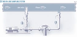
Locating the sampler and the densitometer in the same process stream or loop provides the best means of achieving such representativity.
Traditional sampling and metering systems often installed their instruments with the sampler upstream of the meter bank, adding densitometers in loops taken off downstream of the meter bank (Fig. 1). Such systems clearly introduce the possibility of the water content, and therefore the density, at each point being different.
Figs. 2 and 3 illustrate alternative systems.
IP and other equivalent density standards require that all considerations of the Sampling Standards (IP 6.2, ISO 3171) be taken into account for oil service, meaning that the sampling process and the measurement of density must be considered simultaneously.
The three steps ensuring compliance are:
- Pipeline mixing.
- Representative off-take and maintaining representativity in the off-take system through the measurement devices.
- Sample handling and analysis (for the sampling function only) or the performance of the on-line analyzer.
Before consideration is given to the overall uncertainty of mass measurement derived from metering and quality systems, the main pipeline must be adequately mixed to prevent the densitometer, sampler, or OWD from under-measuring the water content or the density by taking samples from a single point on the cross section. The uncertainty in this area is always negative, resulting in a loss of product.
Pipeline mixing
All measurements, even those employing a full-bore sensor (a spool) require a well-mixed pipeline. The majority of densitometers, OWDs, and samplers lie in loops extracted from the main pipeline. The quality of the dispersion required relates directly to the measurement methodology. For example ISO 3171 requires that the diameter of the inlet to a sample (quality) loop be 10 times the size of the expected water droplets.
A method of estimating the dispersion quality and droplet sizes forms part of all internationally accepted standards, where the C1-C2 ratio is the water concentration in the top of a horizontal pipe divided by that at the bottom. A C1-C2 ratio above 0.9 is considered adequate for sampling.
The water droplet size relates directly to the rate of energy dissipation and the rate of gravitational fallout (segregation). There is also clearly a relationship between pipeline mixing and the (diameter) size of the inlet to a sampling device or quality loop.
Larger off-take sizes produce lower uncertainties in measurement systems for any given quality of pipeline mixing. IP 6.2 bears this out, with the definition of iso-kinetic sampling widely extended as the size of the off-take loop is increased.
A hierarchy of sampling methods can minimize uncertainty, starting with the highest uncertainty:
- In-tank sampling.
- Shipboard sampling.
- In-line sample probes.
- Large-bore fast loop samplers.
- CoJetix sampling systems.
Inadequate pipeline mixing makes the uncertainties of a sampling device or quality loop irrelevant because the sample taken cannot be representative.
Off-take loop
A correctly designed quality loop will consistently outperform an in-line device. More than 100 water-injection tests (including failures) of sampling systems in a variety of configurations yielded the results shown in Table 1.
Once a representative stream has been created, the quality loop must remain representative. This requirement can lead to two problems: the first, ensuring the flow rate in the loop maintains the stream in an adequately dispersed state; and the second, ensuring that the stream properties are not changed due to pressure or temperature effects, including rvp issues and cavitation.
Physical sampling
These issues apply only to physical sampling methodology and its requirements for collection, retention, sub-sampling, and analysis. This sequence consists of three parts: collection, sub-sampling, and analysis.
Collection
The sample needs a receiver capable of retaining the sample in state without depleting the quality being studied. This means providing clean receivers without water traps and with the ability to ensure no loss of light ends. Temperatures affect light-end loss, potentially cooking samples in a desert environment. Attempting a sub-sample in such an environment, even under pressure, can result in a significant volume of light ends being blown off, leading to both a lower API result than the bulk volume and water vapor.
Sample mixing
The mixing and sub-sampling process also requires care because the mixing tends to change density so much that some companies take density samples from hand-agitated receivers only, returning the density sample to the receiver before mixing for water content.
In a test on Middle East crude, a sample container and mixer were circulated continuously and density samples drawn every 5 min for 1 hr, resulting in a 40-point shift density.
IP, API, and ISO all point out that the number of sub-sampling processes should be minimized because each step in the process adds uncertainty. Fixed receiver systems are far from ideal. The use of field-mounted fixed receivers also has practical limitations brought about by the removal of a key measurement process from a laboratory to a field environment.
Sample analysis
The de facto standard is Karl Fischer for water and either a wet bob or an Anton Parr densitometer for the laboratory. The wet bob method requires diligence to correct to normalized conditions.
All steps require equal attention because uncertainty generated by any of the steps will yield uncertainty in the overall result.
Uncertainties
Several sources of uncertainty exist in the mass calculation, beyond those created by the metering (volumetric) element itself. Such uncertainty relates to the correct measurement of density and the correct measurement of the water content in the batch.
Poor pipeline mixing results in both poor water content measurement and poor density measurement of the sample. Poor measurement of density as a result of changes in the physical characteristics of the fluid (as compared to volumetric metering) can also cause uncertainty.
Pipeline mixing
Taking the sampling and density measurements from the same process stream can reduce the uncertainty in the overall mass.
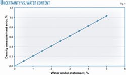
If the recorded density relates correctly to the recorded water content, a correct balance can be achieved. If the recorded density is lower, however, for example because the density loop has a lower water content than that produced by the sampling system, then the total mass of oil will be understated (Fig. 4).
Poor measurement
A variety of sources can cause density-measurement errors.
In the example given, separating the density-measurement system from the sampling system made it subject to potential error. Poor conditioning within the quality loop can also reduce the likelihood of a correct density reading. For a metering system to accurately total mass, the IP density standard requires that the density measurement be made at conditions close to the metering process. Pipeline condition and physical changes that can occur in the quality loop, and are often simply overlooked, can affect the uncertainty in density measurement.
An overall density uncertainty of 0.1% should not yield errors arising from pressure and temperature greater than 0.03%. If the correct fluid enters the quality loop, changes in temperature and pressure can alter its physical properties. Table 2 shows the sensitivities of crude oil with a nominal density of 850 kg/cu m. Correctly adjusting density to process conditions at the flowmeter (pressure and temperature) allows adjustment of these figures.
Further changes in the physical properties, for which no compensation can be made, can also influence these uncertainties. These would include either significant changes in temperature or pressure or suction losses that may cause gassing of the oil.
Density errors
The increasing tendency to use OWD systems make it important that any water-in-oil monitor using a dielectric constant upon which to base the water content compensate for the “dry oil” dielectric, including microwave-based techniques.
Several vendors suggest that the dry-oil dielectric constant can be ascertained by measuring the density of the process stream, but this a wet-oil stream, so the meter is actually compensated using the wrong density.
While using an erroneous density for compensation may not generate huge errors, they are significant enough to preclude using this technology for import terminals subject to a wide range of oil types.
They can, however, operate successfully as part of an export system. This is because the uncertainty in the overall measurement increases disproportionately to the changing water content and design failures become more evident as production rates fall.
Density loops
Many operators have installed many densitometer loops with their off-take from the side of the pipeline (with no due consideration of the representivity of the source), on the suction sides of pumped loops, or in loops that have insufficient velocity to maintain process equilibrium.
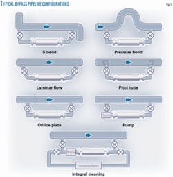
Manufacturers’ suggestions also offer little guidance regarding how to gather a representative sample (Fig. 5).
That quality loops are often convoluted designs, engineered into small spaces, and often with long and undersized suction lines, makes significant pressure and temperature offsets between the metering point and the densitometer not unusual.
Restricted piping and the poor consideration of temperature losses, as well as low-NPSH pumping conditions, and local hotspots within pumps, make a temperature offset of 0.2 K. between the metering location and the densitometer an extremely good result.
Density-measurement-quality loop designs often overlook two key components:
- The representativity of the quality loop in regard to accurate water content.
- The ability of the quality loop’s contents to maintain process conditions adequately to represent the process conditions at the measurement point (i.e. avoiding pressure and temperature offsets).
Densitometer design
Densitometer loops’ original design used a pressurized pyknometer as the proving method with two densitometers, one installed as the recording instrument and the second in parallel as a standby.
Industry practice changed, making the substitution method the preferred method. The densitometer signals (one reference, one comparator) are continuously compared and at a regular interval a unit is replaced with a transfer standard calibrated instrument. For this to operate correctly, however, the densitometers should be in series.
Failure to account for splitting the loop can lead to inadequate flow and difficulty maintaining good temperature stability or ensuring that the parallel streams are subject to the same water content (Fig. 6).
Practicality requires that the density-sampling water-in-oil monitor loops are consistently referenced. Separating the density measurement from the sampling function creates doubt as to whether the figures will match.
The author
Mark Jiskoot is managing director of Jiskoot Ltd., a business supplying pipeline sampling, blending, and multiphase metering solutions to the oil, gas, and petrochemical industries. He assumed his current role in 1991, following stints as Jiskoot’s technical director, sales director, and 5 years in the US establishing Jiskoot’s Houston operations. Jiskoot received a degree in mechanical engineering from Imperial College , London, in 1980.


