REFINERY REVAMP-Conclusion: Crude unit revamp allows refiner to process more low-cost feeds
A revamp of the crude unit in ConocoPhillips’ Ponca City, Okla., refinery has allowed the refiner to process a lower-cost slate and increased overall refinery profitability.
This article, the second of two, discusses the overhead vacuum system design, crude preheat train modifications, execution of the construction and turnaround phases, and results due to the revamp.
The first article (OGJ, Aug. 21, 2006, p. 49) discussed the project’s front-end processing, vacuum tower design, and vacuum heater design.
The Ponca City revamp has met or exceeded ConocoPhillips’ performance expectations. The refiner can process greater amounts of less-expensive crudes, can fully charge a previously underutilized FCC unit, and has benefited from a faster payback time due to higher refining margins.
Overhead vacuum system
The overhead vacuum system was designed to maintain a vacuum tower overhead pressure of 27 mmHg, which corresponds to a target flash-zone pressure of 37 mmHg. The most difficult aspect of properly sizing a vacuum tower overhead system is predicting the cracked-gas rate. Typically, cracked-gas rates range from 0.3 wt % to more than 1.0 wt % (wt % cracked gas vs. vacuum heater feed).
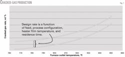
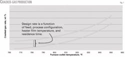
Cracked-gas production is a function of furnace outlet temperature, peak furnace oil-film temperatures, furnace residence time, and crude stability. The cracked-gas design basis for this project was defined based on internal ConocoPhillips empirical data combined with individual reference points from recent projects.
Fig. 1 shows the impact of cracked-gas production vs. furnace outlet temperature. Cracked-gas production increases quite rapidly at furnace outlet temperatures greater than 800° F. Empirical relationships can be helpful for estimating cracked-gas rates; however, actual performance depends highly on the unique combination of crude slate and specific unit design parameters. When available, test data are always preferred to ensure that the vacuum system is large enough for the application.
One unique feature of the Ponca City crude unit is the presence of an intermediate flash tower, located between the atmospheric and vacuum units. This tower takes reduced crude from the atmospheric tower bottoms, reheats it using an intermediate heater, and flashes off an additional gas oil product before the reduced crude flows to the vacuum heater.
The added reheat step and additional residence time at high temperatures may lead to some additional instability in the vacuum unit feed, which can also result in higher-than-expected cracked gas production.
The final vacuum system’s size was based on a relatively conservative cracked-gas rate of nominally 0.7 wt % of feed at a heater outlet temperature of 780° F. This design basis allowed the Ponca City crude unit to have the flexibility to handle changing feed characteristics.
The vacuum system equipment was designed for operational flexibility and optimization. A three-stage system was installed with three parallel ejectors on the first stage and two parallel ejectors on the second and third stages.
This configuration allows one or more ejectors to be taken out of service when cracked-gas loads dictate, which minimizes steam requirements for the system. A kickback recycle from the first-stage discharge to the first-stage suction allows pressure control with changing vacuum tower overhead rates.
Crude preheat train
One area where operational flexibility is critical is in the crude preheat train.
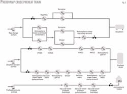
Fig. 2 shows the crude preheat train before the revamp.
The Ponca City No.1 crude unit’s preheat train includes three sections:
- Heat exchange with light products before the desalter.
- Heat exchange with intermediate products from the desalters to the atmospheric tower preflash.
- Heat exchange with heavier products vs. preflash bottoms.
During postrevamp crude unit operations, significantly more heat is available at the unit’s back end where heavy vacuum gas oil (HVGO) pumparound duty and vacuum tower boot quench rate are significantly higher. These increased duties required the installation of additional heat-transfer area for HVGO vs. crude service and vacuum resid vs. crude.
The crude preheat design also required optimization of overall heat recovery vs. the vacuum tower flash-zone pressure. A lower flash-zone pressure is generally preferred because it allows a lower furnace-outlet temperature at equivalent flash-zone vaporization. A lower operating pressure, however, also results in lower gas-oil draw temperatures, which can significantly affect the crude preheat design.
Once the optimum vacuum tower flash-zone pressure was set, a simplified pinch analysis optimized the location of new exchangers given a variety of conditions. Rather than designing new exchangers for a single, worst-case scenario, the system was designed for operational flexibility given a range of current and future crude slates.
A rigorous pinch analysis, while ideal for a grassroots installation, is not always realistic for a unit revamp. Revamp design must consider the practical aspects of the existing unit, including overall layout, exchanger network configuration, and revamp constructibility.
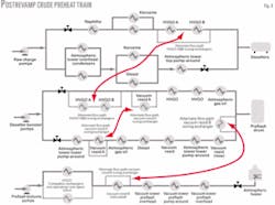
The heat train analysis identified areas where the system’s flexibility could improve by having the capability to shift heat loads from one section of the heat train to another. For example, one piping modification allowed exchangers located downstream of the desalters to shift to an upstream position. This swing configuration allows the refiner to increase desalter temperature as required to maintain desalter performance when heavier crudes are fed to the unit.
Additionally, the piping to an existing resid exchanger was modified to allow swing operation from downstream of the preflash drum to a location upstream. This configuration allows the refiner to adjust the preflash temperature as required for various feeds.
Finally, heat train flexibility was implemented for vacuum resid cooling. This was required to allow maximum resid cooling during a coker outage scenario when vacuum resid must be sent to storage.
Fig. 3 shows the crude preheat train after the revamp.
Having the process flexibility to shift heat duties within the preheat train allows the refiner to process a wide range of crude slates, while maintaining high energy efficiency and optimum desalter and preflash performance. Adding flexibility to the design, rather than just adding excess exchanger surface area, results in improved long-term profitability with minimal capital investment.
One unique application of the Ponca City revamp was use of an Alfa Laval Compabloc heat exchanger in the new HVGO vs. crude service. The available plot space near the existing HVGO exchangers was limited, and significantly more exchanger surface area was required due to the large increase in HVGO product flow.
Compabloc exchangers are fully welded, cross-flow plate heat exchangers that provide high heat-transfer coefficients in a small, compact unit. Because the application was new to ConocoPhillips, two Compabloc exchangers were installed in parallel. The second exchanger was designed to function normally as a spare but was also considered for parallel operation during certain operating modes when the refiner had to maximize HVGO duty.
Even with the installation of a full-sized spare, the two Compabloc exchangers required less plot space than the multiple shell-and-tube exchangers that would have been required to achieve the same duty. The installed exchangers each contain more than 2,100 sq ft of surface area with a design duty of approximately 27 MMbtu/hr.
Construction, turnaround execution
A key economic requirement in the crude-vacuum unit revamp was to complete construction during a normally scheduled turnaround. Based on layout constraints in the unit, the major pieces of new equipment including the vacuum tower, vacuum heater, and overhead vacuum system, had to be installed in the same location as the existing equipment. This required the demolition of old equipment and the installation of new to be performed during the turnaround.
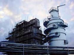
Before the turnaround, the new vacuum tower and vacuum heater were fully erected on temporary foundations, and completely dressed to the maximum extent possible (Fig. 4).
Complete installation of all tower internals, insulation, instrumentation, ladders, and platforms was performed before the turnaround. The vacuum heater box was fully assembled; the heater design allowed the entire unit (except the stack) to be moved from the temporary foundation to its final location in a single lift.
In the first 10 days of the turnaround, the old vacuum tower and heater were removed and the new tower and heater set in place on the existing foundations.
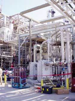
In addition to the new tower and heater, turnaround activities included the installation of three new crude preheat exchangers (one shell-and-tube, and two Compabloc exchangers (Fig. 5)), the relocation of one existing shell-and-tube exchanger, the installation of a new three-stage overhead vacuum system, two new HVGO pumps, and more than 5,700 ft of piping modifications.
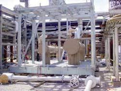
The steam ejector vacuum system was field assembled onto a single skid incorporating the large first and second-stage ejectors and heat exchangers. This allowed the majority of the new vacuum system to be installed in a single lift (Fig. 6).
Revamp results
The revamped crude and vacuum unit started up in November 2004. The key project objectives were to improve the refinery’s capability to process less-expensive crudes and to increase vacuum gas oil recovery to take advantage of spare FCC capacity.
Based on these objectives, the project results are simple-the unit is fully capable of running 100% “advantaged” crude and the incremental gas oil produced has completely filled all spare FCC capacity. In a nominal market, the project was expected to provide good earnings with an approximate 2-year simple payback. With the market conditions of 2005-06, however, return on capital has well exceeded expectations.
The Ponca City refinery runs a continuously variable crude slate. This fact, combined with other refinery factors that affect day-to-day operations, makes it difficult to draw exact apples-to-apples comparisons between pre and postrevamp performance.
The results are presented using two bases for comparison. The first is a review of data for the 2-month period of May-June 2004 (peak gasoline season) vs. the same period in 2005. This comparison provides a basis for which seasonal factors for refinery operations would be roughly similar.
The second basis compares the best 7-day average of 2004 with the best 7-day average of 2005 for each performance variable.
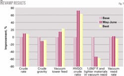
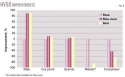
Figs. 7 and 8 show some of the overall unit feed and product results, and results specific to the increased production of HVGO.
In an overall feeds-products comparison, the key performance indicators include overall charge rate, crude API gravity, vacuum tower feed rate, ratio of HVGO recovered vs. crude charge, weight percent of 1,050° F. and lighter materials in the vacuum resid, and vacuum resid rate.
Capacity increase was not an objective in the project’s design basis. During front-end loading, it was acknowledged that a slight rate increase could be expected due to the revamp design’s inherent flexibility. The May-June comparison data reflect a crude rate increase of nominally 10% after the revamp, with a corresponding reduction in API gravity of 11%. The best-of comparison showed the same directional improvements, though slightly smaller in magnitude (9% and 7%, respectively).
For the May-June data, vacuum tower feed increased 15% in 2005 vs. 2004; this increase was 23% comparing the best of 2005 vs. 2004. HVGO-to-crude ratio increased more than 70% and 60%, respectively, from 2004 to 2005, for the two comparison bases. For the weight percent of 1,050° F. and lighter material in the vacuum resid, the results were independent of the basis with reductions of 54% and 56%, respectively.
The vacuum resid rate in the two comparisons was essentially unchanged at +3% and -4%. This result is consistent with the design objective of increased gas oil recovery while maintaining a fixed limit for vacuum resid feed to the coker.
For HVGO product and quality, key performance indicators include HVGO rate, cut point, API gravity, and metals and concarbon content. Both comparisons show an HVGO rate increase of nominally 90% postrevamp. HVGO cut point showed a 9% increase in the May-June comparison, with this figure being 7% when comparing the best-of results.
Cut point alone does not demonstrate the true performance of a vacuum tower. Gas-oil quality is critical and has a significant economic influence in downstream units. Metals content (nickel plus vanadium) decreased dramatically postrevamp (85%), with a concurrent reduction in concarbon residue of 40-60%. A further illustration of this improvement is a reported change in appearance of the HVGO product; it changed from a black or very dark green prerevamp to a transparent dark amber postrevamp.
A final area of interest was the performance of the Compabloc exchangers, which were installed in HVGO vs. crude preheat service. These exchangers were selected due to limited plot space availability and lower total installed cost. The key controlling factor for these exchangers has been crude-side pressure drop (HVGO-side pressure drop has not noticeably increased).
The first exchanger exhibited a run length of about 5 months before operations decided to switch to the spare exchanger due to hydraulic limitations. Crude-side pressure drop on the second exchanger appears to be increasing at a slower rate than was observed on the first unit, perhaps indicating some start-up plugging that may have occurred on the first exchanger.
Despite the increased pressure drop, heat duty performance for the exchangers has been relatively constant.
Currently, the ConocoPhillips operations department is experimenting with online cleaning alternatives. An initial attempt in September 2005 using light cycle oil circulation provided mixed results. The manufacturer expects, however, that online cleaning will offer acceptable results once a fit-for-purpose cleaning procedure is established. Mechanical cleaning (hydroblasting) is also an alternative because the exchanger side plates are fully removable to allow mechanical cleaning.
Acknowledgments
The authors thank the many personnel who helped make this project successful, including the ConocoPhilips in-house fractionation consultants, the Ponca City West Plant operators and area engineers, and the project’s many engineering and administrative personnel at both ConocoPhillips and Burns & McDonnell.
Based on a presentation to the National Petrochemical & Refiners Association Annual Meeting, Salt Lake City, Mar. 19-21, 2006.
