Micropilot tests progress, durability an issue
Retrofit diesel pilot ignition (DPI), or micropilot, systems installed on natural gas pipeline compressor engines can deliver efficiency and emissions improvements when compared to spark ignition systems.
This article examines the design, installation, and testing of a 10-cylinder DPI prototype at an operating compressor station.
The engine operated more stably with fewer misfires and partial combustion events than spark-ignition. But injector fouling may have degraded performance assessment, and the performance benefits may be understated. Despite custom injector cooling adaptors, the micropilot injectors failed the durability test.
System description
The US pipeline industry uses about 8,000 reciprocating engines for natural gas compression, with a combined capacity of 7 Gw (9.4 million hp). The overwhelming majority of these engines are low-compression ratio, slow-speed, large-bore, low brake-mean-effective-pressure, 2-stroke gas engines. Almost all of these engines are between 20 and 50 years old. To replace any significant fraction of them would cost billions of dollars, making retrofit technologies for improving the performance of these engines very important.
An emerging technology for industrial natural gas reciprocating internal combustion engines is pilot ignition with extremely small quantities of pilot fuel. Colorado State University’s Engines and Energy Conversion Laboratory has been developing this technology for about 4 years.
DPI systems are natural gas reciprocating internal combustion engines with a small-quantity pilot ignition. The basic principle of operation is the same as for a dual-fuel engine operating in natural gas-diesel mode. A DPI system, however, generally uses less than 2% pilot fuel on an energy basis to ignite a premixed natural gas and air charge. Compression ignition initiates the combustion, but combustion of more than 98% of the fuel energy occurs with spark ignition (premixed) combustion characteristics.
Off-the-shelf technology makes up the DPI system for large-bore natural gas engines used in this article. The main components in the DPI system are:
• Fuel storage system.
• High pressure fuel pump.
• Fuel distribution manifold.
• Fuel injectors.
• Injector current driver.
• Control system (specifies injection-ignition timing, injection duration, and fuel pressure).
• Pressure control valve.
• Sensors (fuel pressure, fuel temperature, speed, and top dead center).
The injectors, pump, and other components from the primary fuel system of a European Ford Focus diesel engine were adapted for use as a retrofit DPI system for natural gas compressor engines. The hardware and manpower costs associated with installing the system on an engine are comparable to those for the installation of a pre-combustion chamber ignition system, a major component of low-emission combustion technology.
Micropilot benefits
DPI provides multiple distributed ignition sites within the engine cylinder. This helps combustion in several ways, including improving combustion stability and increasing the rate of combustion.
• Combustion stability improvements. DPI’s distributed ignition sites are away from the cold combustion chamber wall, increasing the probability of effectively initiating combustion. This is particularly true in circumstances where the fuel and air mixture in the cylinder is not homogeneous.
A single ignition site introduces a significant probability of ignition occurring where the air and fuel mixture is too lean to ignite or burn efficiently. Additionally, with DPI, droplets or jets of liquid pilot fuel burning as diffusion flames create ignition, distinctly different from the plasma created by a high-voltage spark in a single-spark ignition site. Distributed ignition sites greatly improve the probability of effective combustion ignition, stabilizing combustion from cycle-to-cycle.
• Increased rate-of-combustion. Distributing ignition sites within the cylinder causes the reactants to burn from multiple locations simultaneously. Flame propagation from an elongated ignition site creates a similar situation. Multiple flame fronts consume reactants, increasing the rate of combustion. Faster combustion results in a more rapid pressure increase, more closely approximating constant volume combustion and increasing engine efficiency.
Laboratory results
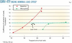
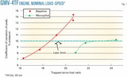
The combustion enhancements described in the previous section have a significant effect on engine performance and emissions. Laboratory engine testing at the EECL, with the Cooper-Bessemer GMV4-TF large-bore natural gas engine, showed a 2.5% reduction in fuel consumption at 16.5 in. Hg (trapped air-to-fuel = 22), with the diesel fuel energy part of the fuel consumption for the DPI configuration. A coefficient of variation of peak pressure of 10% as the lean limit definition extended the lean limit of combustion by about 4.5 air-to-fuel units (18.5 to 23; Fig. 1).
Changing the air manifold pressure at constant load and speed varies the trapped air-to-fuel ratio. The pilot fuel injection quantity, pressure, and timing of each micropilot are optimized to reduce nitrogen oxides and reduce specific fuel consumption. This extended lean limit reduced NOx emissions by more than 6 g/bhp-hr, to less than 2 g/bhp-hr from about 8 g/bhp-hr.
The stock compression ratio configuration (8.4) required a minimum pilot fuel quantity of 16 microliters (μl.), 1% of total fuel energy. We increased the compression ratio from 8.4 to 9.1 by adding a spacer beneath the piston and machining off material from the perimeter of the piston crown for clearance, reducing the minimum pilot fuel quantity required to 6 μl., about 0.33% of the total fuel.
Field testing
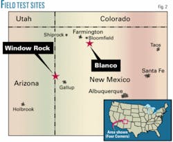
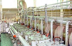
We sought field-test sites which had a high level of support and had compressor engines in consistent operation. Two host sites satisfied these criteria, both owned by El Paso Natural Gas (Fig. 2). The first site, at Window Rock, Ariz., involved the retrofit of a Worthington SUTC-10 (Unit 4A), 2,500-hp engine. The second site, at Blanco, NM, used a Cooper-Bessemer GMV-10TF.
A consortium of the Woodward Governor Co., Hoerbiger Corp. of America, Enginuity LLC, and DigiCon, Inc. provided the fuel-system hardware. Woodward furnished the electronics, the pilot fuel injectors, and the fuel pump. Hoerbiger provided the wiring harness, fuel rail, injector cooling adaptors, and fuel supply-return piping. Enginuity designed and fabricated the control and injector driver systems. DigiCon sized the fuel supply system and other system components. CSU personnel fabricated the pump module at the EECL and shipped the unit to the site. CSU personnel also designed a special tool for installing the injector adapter within the existing spark plug hole.
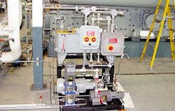
Figs. 3-5 show the installed DPI system components. Hoerbiger managed field installation.
Pipeline engines need to retain their spark ignition systems for startup, until sufficient engine heat is developed for compression ignition of the pilot fuel, at which time the spark ignition system can be deactivated. Automated systems controlled this function, as well as pilot fuel injection pressure, timing, and duration. Enginuity commissioned the control system.
The engine’s first operation on DPI was relatively problem-free. All on-engine components functioned properly and some diesel-transfer system enhancements were identified. The consortium implemented these enhancements, allowing automatic filling of the pump module from the 1,000-gal. diesel storage tank outside the engine room, shortly after initial commissioning, and Unit 4A was restarted with the micropilot ignition system operational.
Unit 4A operated for about 1 month with the retrofit DPI system, with the auxiliary spark plug active. A varnish-like residue created by overheating of the diesel fuel fouled some of the injectors. The consortium changed-out the injectors and conducted emissions and performance tests. Fouling of several replacement injectors forced deactivation of the DPI system pending a long-term solution to the fouling problem. It is unclear whether the injectors failed gradually or abruptly. It is possible that some of the injectors were not fully functional during performance testing.
An electric solenoid that opens a pilot valve, allowing pressurized fuel to flow into the chamber with the pintle, operated the injectors used in the DPI testing. The pressurized fuel lifts the pintle off its seat against a return spring. Once lifted, the pintle allows the pressurized fuel to exit the nozzle in an atomized mist. An overheating of the injector nozzle caused the failure mode seen at Window Rock.
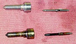
The nozzle overheated to the point that the fuel inside began to break down, creating a carbon powder and varnish coating on the pintle inside the nozzle. Since diesel injectors have extremely tight tolerances, a very small amount of foreign material (including broken down fuel) will sieze the pintle in the nozzle. Fig. 6 shows the carbon-varnish buildup by comparing nozzle-pintle sets before and after they were operated in the engine.
Operational limitations of the Cooper-Bessemer GMV engines at the Blanco site prevented field-testing at that location. These engines have a low compression ratio (7.5), low-boost (piston scavenged, 1.5 in. Hg), and low brake mean effective pressure (56 psi).
The technology plan for the Blanco site included lube oil as the pilot fuel, instead of diesel, due to the lower self-ignition temperature of lube oil. EECL personnel conducted a single-cylinder injection-ignition test at Blanco but were unable to achieve autoignition of the lube oil due to low compression pressures and temperatures.
EECL personnel then installed a high-compression ratio head on one cylinder to mitigate these conditions but encountered mechanical interferences. Accommodating the high-compression ratio heads would require removing and machining all 10 power pistons. These substantial modifications, inconsistent with the objectives of this program, forced the end of development efforts at the Blanco site.
Test results
CSU personnel with the EECL’s mobile emissions laboratory performed premodification, baseline testing with the stock dual-spark ignition system. After installation of the field test hardware at Window Rock, Woodward and CSU assisted the vendor consortium through startup and shakedown. Running the systems for a few days provided operational experience. Once field-operations personnel were familiar with the equipment a performance test was scheduled. During the performance test, EECL personnel on-site with the mobile emissions laboratory monitored the performance of the engine with the pilot ignition system. The auxiliary spark plug was left on during testing to reduce the chance of a piston failing completely due to injector fouling. One micropilot injector and one spark plug operated for data gathering.
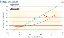
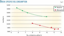
Figs. 7-9 show the data, taken at nominal speed and load. Variability in pipeline conditions prevented an exact match of the load for the two data sets. The micropilot system delivered about 30 µl. per cylinder per cycle at 3,500 psi.
Fig. 7 illustrates that, with the exception of one of the low boost points, combustion stability with DPI is better than with spark ignition, although the differences do not appear as large as with the laboratory testing on the smaller GMV engine. Boost ranged from 16 to 26 in. Hg for the data shown.
Fuel consumption (Fig. 8) improved significantly. The micropilot fuel consumption data represents the sum of the energy from natural gas plus the energy from the pilot fuel.
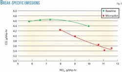
Fig. 9 contains a cross plot of CO emissions vs. NOx. For the same NOx emission level, the micropilot data display a reduction in CO emissions. Increasing the trapped air-to-fuel ratio, however, elevated CO emission levels. There were no major repairs carried out between the baseline and micropilot testing; therefore the comparison between the two data sets is assumed valid.
Durability testing
The limited durability of the pilot fuel injectors made it difficult even to obtain performance data. The auxiliary spark operated during performance testing.
Theses difficulties led to a significant effort to resolve the injector tip cooling problems. A new injector cooling adaptor design was developed. New injector tip heat sinks were installed; copper sleeves that fit around the injector tip and aid in the transfer of heat away from the tip. A new set of injectors was also procured.
EECL conducted a second test program with the new hardware. The engine ran on DPI only for 72 hr continuously, showing improved injector cooling but not complete alleviation of the problem.
The injectors failed the durability test. For the system practicality, the injectors must last significantly longer than a spark plug (2,000 hr).
Acknowledgments
The Gas Technology Institute, Department of Energy, El Paso Corp., and the Pipeline Research Council International funded the work described in this article. The authors acknowledge the technical support and in-kind contributions of the vendor consortium: Woodward Governor Co., Hoerbiger Corp. of America, Enginuity LLC, and DigiCon Inc. Finally, we express our appreciation to the many undergraduate and graduate students who have made contributions to this work, including Ted Moosman, Jason Komoroski, and Scott Chase. ✦
Bibliography
Brown, J., “On-engine Investigation of a Micro-liter Quantity Pilot Ignition System for a Large-bore Natural Gas Engine,” Masters thesis, Colorado State University, Fort Collins, Colo., 2003.
Brown, J., Mizia, J., Olsen, D.B., and Willson, B.D., “On-engine Demonstration of a Micropilot Ignition System for a Cooper-Bessemer GMV-4TF,” ASME-ICE Fall Technical Conference, Erie, Pa., Sept. 7-10, 2003.
Chase, S.A., Olsen, D.B., and Willson, B.D., “Investigation of Micropilot Fuel Ignition Systems for Large-bore Natural Gas Engines,” GMRC Gas Machinery Conference, Albuquerque, NM, Oct. 4-6, 2004.
Mizia, J., “Micro-liter Quantity Pilot Injections Studies in a Constant Volume Combustion Test Chamber, Masters thesis, Colorado State University, Fort Collins, Colo., 2003.
The authors
Daniel Olsen is a Research Scientist at the Colorado State University (CSU) Engines and Energy Conversion Laboratory. He manages large bore natural gas engine research projects and teaches thermal science courses in the mechanical engineering department. Prior to coming to CSU in 1995 he worked in industry for 6 years as a design engineer. He holds a Ph.D. in Mechanical Engineering from Colorado State University.
Kirk H Evans (kirk.evans@ colostate.edu) is lab manager at Colorado State University Engines & Energy Conversion Laboratory. He holds a bachelors degree in mechanical engineering from Colorado State University and an associates degree in applied science from Garden City Community College.
Mark Noall is a reliability engineering superintendent for El Paso Plant Services in Midland Texas. His responsibilities include technical support for reciprocating engine and gas turbine engine driven compressors for El Paso’s main line compressor stations in southwest Texas. Noall has 24 years of experience in the energy industry. The primary focus of his work experience is with the efficient and reliable operation of pipeline compressor stations. He received his BS in mechanical engineering from BYU in1982.
